
Page 257 - Wind Energy Handbook
P. 257
BLADE LOADS DURING OPERATION 231
As explained in Section 3.12, the phenomenon of stall delay results in significantly
increased values of the lift coefficient at higher wind speeds on the inboard section
of the rotating blade than predicted by static aerofoil data, such as that reproduced
in Figure 3.41. Accordingly, Figure 5.8 and the other figures referred to in this
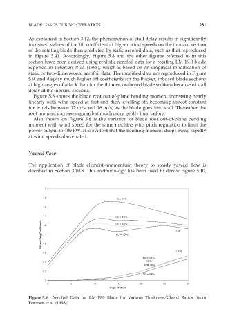
section have been derived using realistic aerofoil data for a rotating LM-19.0 blade
reported in Petersen et al. (1998), which is based on an empirical modification of
static or two-dimensional aerofoil data. The modified data are reproduced in Figure
5.9, and display much higher lift coefficients for the thicker, inboard blade sections
at high angles of attack than for the thinner, outboard blade sections because of stall
delay at the inboard sections.
Figure 5.8 shows the blade root out-of-plane bending moment increasing nearly
linearly with wind speed at first and then levelling off, becoming almost constant
for winds between 12 m=s and 16 m=s, as the blade goes into stall. Thereafter the
root moment increases again, but much more gently than before.
Also shown on Figure 5.8 is the variation of blade root out-of-plane bending
moment with wind speed for the same machine with pitch regulation to limit the
power output to 400 kW. It is evident that the bending moment drops away rapidly
at wind speeds above rated.
Yawed flow
The application of blade element–momentum theory to steady yawed flow is
decribed in Section 3.10.8. This methodology has been used to derive Figure 5.10,
2
1.8 t/c = 24%
1.6
1.4 t/c = 18%
Lift and Drag Coefficients 1.2 1 t/c = 13% Lift
t/c = 15%
0.8
Drag
0.6
t/c = 13%,
0.4 15%
and 18%
0.2
t/c = 24%
0
0 5 10 15 20 25 30
Angle of attack
Figure 5.9 Aerofoil Data for LM-19.0 Blade for Various Thickness/Chord Ratios (from
Petersen et al. (1998))