
Page 256 - Wind Energy Handbook
P. 256
230 DESIGN LOADS FOR HORIZONTAL-AXIS WIND TURBINES
300
Rotational speed = 30 rpm
250
200
Bending Moment (KNm) 150 Out-of-plane moment
100
50
In-plane moment
0
0 2 4 6 8 10 12 14 16 18 20
Radius (m)
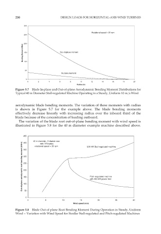
Figure 5.7 Blade In-plane and Out-of-plane Aerodynamic Bending Moment Distributions for
Typical 40 m Diameter Stall-regulated Machine Operating in a Steady, Uniform 10 m=s Wind
aerodynamic blade bending moments. The variation of these moments with radius
is shown in Figure 5.7 for the example above. The blade bending moments
effectively decrease linearly with increasing radius over the inboard third of the
blade because of the concentration of loading outboard.
The variation of the blade root out-of-plane bending moment with wind speed is
illustrated in Figure 5.8 for the 40 m diameter example machine described above.
450
40 m diameter, 3 bladed rotor 500 kW Stall-regulated machine
Out-of-plane aerodynamic root bending moment (kNm) 300 Pitch-regulated machine
400
with TR blades
rotational speed = 30 rpm
350
250
200
150
with 400 kW power limit
100
50
0
0 5 10 15 20 25 30
Wind speed (m/s)
Figure 5.8 Blade Out-of-plane Root Bending Moment During Operation in Steady, Uniform
Wind – Variation with Wind Speed for Similar Stall-regulated and Pitch-regulated Machines