
Page 251 - Wind Energy Handbook
P. 251
STATIONARY BLADE LOADING 225
1
0.8
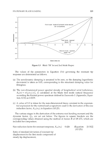
First mode - blade of constant cross section
(for comparison)
0.6
0.4
Displacement 0.2
First mode - tapered
blade ‘TR’
0
0 2 4 6 8 10 12 14 16 18 20
-0.2
Second mode - tapered
blade ‘TR’
-0.4
-0.6
Blade radius (m)
Figure 5.3 Blade ‘TR’ 1st and 2nd Mode Shapes
The values of the parameters in Equation (5.6) governing the resonant tip
response are determined as follows.
(a) The aerodynamic damping is assumed to be zero, so the damping logarithmic
decrement is taken as 0.05, corresponding to the structural damping value for
fibreglass.
(b) The non-dimensional power spectral density of longitudinal wind turbulence,
2
R u (n) ¼ nS u (n 1 )=ó , is calculated at the blade first mode natural frequency
u
according the Kaimal power spectrum defined in Eurocode 1 (Appendix, Equa-
tion A5.8) as 0.0339.
(c) A value of 9.2 is taken for the non-dimensional decay constant in the exponen-
tial expression for the normalized co-spectrum used in the derivation of the size
reduction factor, K Sx (n 1 ), in Equation (A5.25).
The various stages in the derivation of the extreme root bending moment and the
dynamic factor, Q D , are set out below. The figures in square brackets are the
corresponding values obtained using the method of Annex B of DS 472, which are
included for comparison.
Size reduction factor for resonant response, K Sx (n 1 ) 0.426 (Equation [0.312]
(A5.25))
Ratio of standard deviation of resonant tip
displacement to the first mode component of
steady tip displacement,