
Page 255 - Wind Energy Handbook
P. 255
BLADE LOADS DURING OPERATION 229
permissible). These equations can be arranged to give the following expressions for
the forces per unit length on an element perpendicular to the plane of rotation and
in the direction of blade motion, known as the out-of-plane and in-plane forces
respectively:
f
1 2 2
1
Out-of-plane force per unit length: F X ¼ C x 2 rW c ¼ 4ðrU (1 af)a N r (5:18)
f
1 2 2
In-plane force per unit length: F Y ¼ C y 2 rW c ¼ 4ðrÙU 1 (1 af)a9 r (5:19)
N
The parameters in the expressions are as defined in Chapter 3 ( f is the tip loss
factor, and N is the number of blades), while the x and y directions are as defined in
Figure C1.
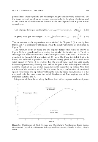
The variation of the in-plane and out-of-plane forces with radius is shown in
Figure 5.6 for a typical machine operating in a steady 10 m=s wind speed. The 40 m
stall-regulated turbine considered in this example is fitted with three ‘TR’ blades as
described in Example 5.1 and rotates at 30 r.p.m. The blade twist distribution is
linear, and selected to produce the maximum energy yield for an annual mean
wind speed of 7 m=s. It is evident that the out-of-plane load per unit length
increases approximately linearly with radius, in spite of the reducing blade chord
until the effects of tip loss are felt beyond about 75 percent of tip radius. Note that
the form of the variation would be the same for any combination of rotational
speed, wind speed and tip radius yielding the same tip speed ratio, because it is the
tip speed ratio that determines the radial distribution of flow angle ö, and of the
induction factors a and a9.
Integration of these forces along the blade then yields in-plane and out-of-plane
1.8
1.6 Out-of-plane force
per unit length
1.4
Rotational speed = 30 rpm
1.2
Load per metre (KN) 0.8 1
0.6
0.4 In-plane force
per unit length
0.2
0
0 2 4 6 8 10 12 14 16 18 20
Radius (m)
Figure 5.6 Distribution of Blade In-plane and Out-of-plane Aerodynamic Loads during
Operation of Typical 40 m Diameter Stall-regulated Machine in a Steady, Uniform 10 m=s
Wind