
Page 258 - Wind Energy Handbook
P. 258
232 DESIGN LOADS FOR HORIZONTAL-AXIS WIND TURBINES
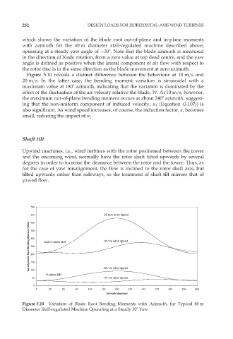
which shows the variation of the blade root out-of-plane and in-plane moments
with azimuth for the 40 m diameter stall-regulated machine described above,
operating at a steady yaw angle of þ308. Note that the blade azimuth is measured
in the direction of blade rotation, from a zero value at top dead centre, and the yaw
angle is defined as positive when the lateral component of air flow with respect to
the rotor disc is in the same direction as the blade movement at zero azimuth.
Figure 5.10 reveals a distinct difference between the behaviour at 10 m=s and
20 m=s. In the latter case, the bending moment variation is sinusoidal with a
maximum value at 1808 azimuth, indicating that the variation is dominated by the
effect of the fluctuation of the air velocity relative the blade, W.At10 m=s, however,
the maximum out-of-plane bending moment occurs at about 2408 azimuth, suggest-
ing that the non-uniform component of induced velocity, u 1 (Equation (3.107)) is
also significant. As wind speed increases, of course, the induction factor, a, becomes
small, reducing the impact of u 1 .
Shaft tilt
Upwind machines, i.e., wind turbines with the rotor positioned between the tower
and the oncoming wind, normally have the rotor shaft tilted upwards by several
degrees in order to increase the clearance between the rotor and the tower. Thus, as
for the case of yaw misalignment, the flow is inclined to the rotor shaft axis, but
tilted upwards rather than sideways, so the treatment of shaft tilt mirrors that of
yawed flow.
500
450 20 m/s wind speed
Aerodynamic Root Bending Moment (kNm) 350 Out-of-plane BM 10 m/s wind speed
400
300
250
200
150
100
In-plane BM 20 m/s wind speed
50 10 m/s wind speed
0
0 30 60 90 120 150 180 210 240 270 300 330 360
Azimuth (degrees)
Figure 5.10 Variation of Blade Root Bending Moments with Azimuth, for Typical 40 m
Diameter Stall-regulated Machine Operating at a Steady 308 Yaw