
Page 278 - Wind Energy Handbook
P. 278
252 DESIGN LOADS FOR HORIZONTAL-AXIS WIND TURBINES
2.5
2 Point 1
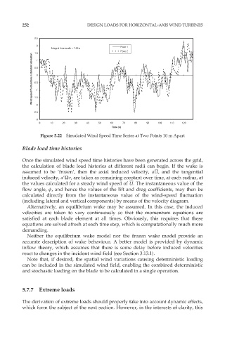
Integral time scale = 7.35 s
Point 2
1.5
Wind speed fluctuations / standard deviation -0.5 0
1
0.5
-1
-1.5
-2
-2.5
-3
0 10 20 30 40 50 60 70 80 90 100 110 120
Time (s)
Figure 5.22 Simulated Wind Speed Time Series at Two Points 10 m Apart
Blade load time histories
Once the simulated wind speed time histories have been generated across the grid,
the calculation of blade load histories at different radii can begin. If the wake is
assumed to be ‘frozen’, then the axial induced velocity, aU, and the tangential
induced velocity, a9Ùr, are taken as remaining constant over time, at each radius, at
the values calculated for a steady wind speed of U. The instantaneous value of the
flow angle, ö, and hence the values of the lift and drag coefficients, may then be
calculated directly from the instantaneous value of the wind-speed fluctuation
(including lateral and vertical components) by means of the velocity diagram.
Alternatively, an equilibrium wake may be assumed. In this case, the induced
velocities are taken to vary continuously so that the momentum equations are
satisfied at each blade element at all times. Obviously, this requires that these
equations are solved afresh at each time step, which is computationally much more
demanding.
Neither the equilibrium wake model nor the frozen wake model provide an
accurate description of wake behaviour. A better model is provided by dynamic
inflow theory, which assumes that there is some delay before induced velocities
react to changes in the incident wind field (see Section 3.13.1).
Note that, if desired, the spatial wind variations causing deterministic loading
can be included in the simulated wind field, enabling the combined deterministic
and stochastic loading on the blade to be calculated in a single operation.
5.7.7 Extreme loads
The derivation of extreme loads should properly take into account dynamic effects,
which form the subject of the next section. However, in the interests of clarity, this