
Page 393 - Wind Energy Handbook
P. 393
DRIVE-TRAIN MOUNTING ARRANGEMENT OPTIONS 367
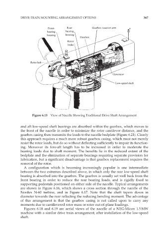
Front- Rear- Gearbox reaction arm
bearing bearing
housing housing
Gearbox
Rotor
brake
Rotor hub
Generator
Low-speed shaft
Figure 6.15 View of Nacelle Showing Traditional Drive Shaft Arrangement
and aft low-speed shaft bearings are absorbed within the gearbox, which moves to
the front of the nacelle in order to minimize the rotor cantilever distance, and the
gearbox casing then transmits the loads to the nacelle bedplate (Figure 6.21). Clearly
this approach requires a much more robust gearbox casing, which must not merely
resist the rotor loads, but do so without deflecting sufficiently to impair its function-
ing. Moreover its fore-aft length has to be increased in order to moderate the
bearing loads due to shaft moment. The benefits lie in the reduced extent of the
bedplate and the elimination of separate bearings requiring separate provision for
lubrication, but a significant disadvantage is that gearbox replacement requires the
removal of the rotor.
A configuration which is becoming increasingly popular is one intermediate
between the two extremes described above, in which only the rear low-speed shaft
bearing is absorbed into the gearbox. The gearbox is usually set well back from the
front bearing in order to reduce the rear bearing loads, and is rigidly fixed to
supporting pedestals positioned on either side of the nacelle. Typical arrangements
are shown in Figure 6.16, which shows a cross section through the nacelle of the
Nordex N-60 turbine, and in Figure 6.17. Note that the shaft tapers down in
diameter towards the rear reflecting the reducing bending moment. The advantage
of this arrangement is that the gearbox casing is not called upon to carry any
moments due to cantilevered rotor mass or rotor out-of-plane loadings.
Figures 6.18 and 6.19 are aerial views of the nacelle of a NEG-Micon 1.5 MW
machine with a similar drive train arrangement, after installation of the low-speed
shaft.