
Page 395 - Wind Energy Handbook
P. 395
DRIVE-TRAIN MOUNTING ARRANGEMENT OPTIONS 369
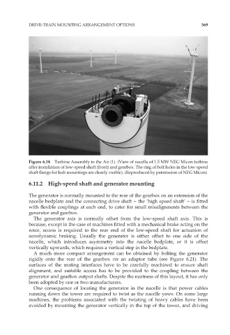
Figure 6.18 Turbine Assembly in the Air (1). (View of nacelle of 1.5 MW NEG Micon turbine
after installation of low-speed shaft (front) and gearbox. The ring of bolt holes in the low-speed
shaft flange for hub mountings are clearly visible). (Reproduced by permission of NEG Micon)
6.11.2 High-speed shaft and generator mounting
The generator is normally mounted to the rear of the gearbox on an extension of the
nacelle bedplate and the connecting drive shaft – the ‘high speed shaft’ – is fitted
with flexible couplings at each end, to cater for small misalignments between the
generator and gearbox.
The generator axis is normally offset from the low-speed shaft axis. This is
because, except in the case of machines fitted with a mechanical brake acting on the
rotor, access is required to the rear end of the low-speed shaft for actuation of
aerodynamic braking. Usually the generator is either offset to one side of the
nacelle, which introduces asymmetry into the nacelle bedplate, or it is offset
vertically upwards, which requires a vertical step in the bedplate.
A much more compact arrangement can be obtained by bolting the generator
rigidly onto the rear of the gearbox via an adaptor tube (see Figure 6.21). The
surfaces of the mating interfaces have to be carefully machined to ensure shaft
alignment, and suitable access has to be provided to the coupling between the
generator and gearbox output shafts. Despite the neatness of this layout, it has only
been adopted by one or two manufacturers.
One consequence of locating the generator in the nacelle is that power cables
running down the tower are required to twist as the nacelle yaws. On some large
machines, the problems associated with the twisting of heavy cables have been
avoided by mounting the generator vertically in the top of the tower, and driving