
Page 394 - Wind Energy Handbook
P. 394
368 CONCEPTUAL DESIGN OF HORIZONTAL-AXIS TURBINES
Hub mounting flange Low-speed shaft
Gearbox mounting
Rotor Front-bearing Gearbox High-speed Cooler
hub housing Brake shaft
Front
bearing
Yaw drive Generator
Safety
Nacelle Yaw brake coupling
bedplate
Figure 6.16 Nacelle Arrangement for the Nordex N60 Turbine (Reproduced by permission
of Nordex)
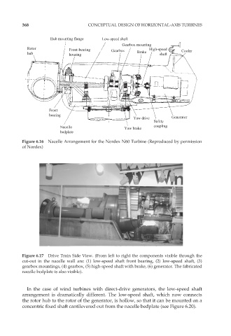
Figure 6.17 Drive Train Side View. (From left to right the components visible through the
cut-out in the nacelle wall are: (1) low-speed shaft front bearing, (2) low-speed shaft, (3)
gearbox mountings, (4) gearbox, (5) high-speed shaft with brake, (6) generator. The fabricated
nacelle bedplate is also visible).
In the case of wind turbines with direct-drive generators, the low-speed shaft
arrangement is dramatically different. The low-speed shaft, which now connects
the rotor hub to the rotor of the generator, is hollow, so that it can be mounted on a
concentric fixed shaft cantilevered out from the nacelle bedplate (see Figure 6.20).