
Page 427 - Wind Energy Handbook
P. 427
BLADES 401
45
40
35 Rotational speed = 17 r.p.m. intensity = 15%,
Percentage contribution per 2 m/s bin 25 16.10% intensity, m = 10
No. of blades = 3
Turbulence
Rotor diameter = 64 m
m = 12
30
Turbulence
intensity = 15%,
m = 10
20
IEC turbulence
15
10 17%
21%
5
0
0 5 10 15 20 25 30
Mean wind speed (m/s)
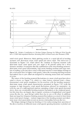
Figure 7.13 Relative Contribution to Life-time Fatigue Damage for Different Wind Speeds
for a 1.5 MW Stall-regulated Machine, Including Effect of Mean Load, after Thomsen (1998)
rated wind speed. Moreover, blade pitching results in a rapid fall-off in bending
moment with short-term mean wind speed just above rated. This behaviour is
illustrated in Figure 7.10, which shows the variation in flapwise moment with
short-term mean wind speed and yaw angle at 60 percent radius for a 40 m
diameter machine. It transpires that the combination of the steep bending moment/
short-term wind speed characteristic, high mean bending moment and large num-
ber of loading cycles just above rated wind speed results in more fatigue damage at
this wind speed than at higher wind speeds, where the increasing bending moment
fluctuations due to yaw offset are mitigated by reducing mean loads and numbers
of cycles.
The nature of the bending moment fluctuations at a mean wind speed just above
rated is shown on Figure 7.14, which is a time history obtained from a three-
dimensional wind speed simulation, for the machine with the bending moment/
short-term mean wind speed characteristics presented in Figure 7.10, (with the
response to high frequency wind speed fluctuations allowed for separately). As
with the case of a stall-regulated machine operating at high wind speed discussed
above, there are considerable bending moment fluctuations at the rotational speed,
but this time they are largely due to spatial variations in longitudinal wind speed
across the disc (i.e., ‘gust slicing’) rather than due to yaw or tilt offset. In addition,
there are large low frequency bending moment fluctuations as a result of short-term
mean wind speed changes – indeed, inspection of the bending moment and short-
term mean wind speed plots reveals an inverse relationship between the two.
The fatigue damage in flapwise bending at 12 m radius arising from operation of
the above machine at different mean wind speeds ignoring dynamics is plotted out