
Page 422 - Wind Energy Handbook
P. 422
396 COMPONENT DESIGN
same time it should be more accurate because of the avoidance of uncertainties
associated with stall. It is instructive to focus comparisons on the blade bending
moment about the weak axis at 60 percent radius once again. This time it is referred
to as the flapwise bending moment rather than the out-of-plane (of rotation)
moment because of blade pitching.
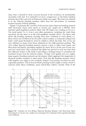
Figure 7.10 presents the variation of 60 percent radius flapwise bending moment
with short-term mean wind speed at several yaw angles for a 500 kW, 40 m
diameter pitch-regulated machine fitted with TR blades and rotating at 33 r.p.m.
The rated speed, V R , is 12 m/s and other parameters, including the wind shear
exponent, are the same as in the stall-regulated example above. The figure only
shows the bending moments resulting from slow variations in wind speed, i.e.,
those which can be followed by the pitch control system, so moments arising from
faster wind speed fluctuations must be added to obtain the total. The curves are
very different in shape from those obtained for the stall-regulated machine. The
12 m radius flapwise bending moment reaches a peak at rated wind speed, and
then drops off sharply, becoming negative by about 24 m/s in the case of zero yaw
and zero wind shear. This is because the blade has pitched to such an extent that
the outboard section of the blade is providing a braking torque to counteract the
increased torque from the inboard section. At high wind speeds and yaw angles,
large negative bending moments are developed, which approach the magnitude of
the peak positive moment at rated speed. Note that the bending moment reduces
with negative yaw angle at zero azimuth, instead of increasing as it does for stall-
regulated operation. This is because blade pitching renders angle of attack, which is
reduced under these conditions, more critical than relative velocity. Plots of the
80
60 Shear exponent = 0.2
Rotational speed = 33 r.p.m.
12 m radius flapwise bending moment (kNm) -20 0 20 yaw 20 yaw
Full-line curves are for 0 azimuth
Dashed lines are for 180 azimuth
40
20
0 yaw,
0
0 yaw,
azimuth
40 yaw,
-40
-60 180 azimuth 20 yaw 180 azimuth
40 yaw, 20 yaw
0 azimuth
-80
0 5 10 15 20 25 30 35 40 45
Wind speed (m/s)
Figure 7.10 Variation of 12 m Radius Flapwise Bending Moment with Short-term Mean
Wind Speed at Various Yaw Angles for an Example 40 m Diameter Pitch-regulated Machine
with TR Blades