
Page 423 - Wind Energy Handbook
P. 423
BLADES 397
variation of flapwise bending moment with short-term mean wind speed at inboard
blade cross sections are essentially similar to those in Figure 7.10, because moments
are dominated by loadings on the outboards portion of the blade.
To the extent that the pitch control system can keep pace with the wind speed
transients, the curves in Figure 7.10 can be used to provide an approximate
indication of the extreme bending moments arising from some of the IEC 61400-1
deterministic load cases. Leaving aside the grid-loss case (where the outcome is
largely determined by rotor inertia and emergency pitching rate), it is seen that the
extreme moments are only about one half of the maximum value for the stall-
regulated machine.
The spectrum of the longitudinal wind speed fluctuations will contain significant
energy at frequencies above the level at which the pitch control system can respond,
and these have to be considered in the analysis of the ‘Normal turbulence model’
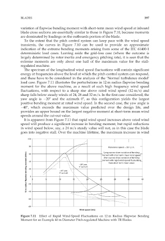
load case. Figure 7.11 illustrates the perturbations in 12 m radius flapwise bending
moment for the above machine, as a result of such high frequency wind speed
fluctuations, with respect to a sharp rise above rated wind speed (12 m/s) and
sharp falls below steady winds of 24, 28 and 32 m/s. In the first case considered, the
yaw angle is 208 and the azimuth 08, as this configuration yields the largest
positive bending moment at rated wind speed. In the second case, the yaw angle is
408, which exceeds the maximum value predicted over the design life, and
provides an upper bound on the largest negative moment at short-term mean wind
speeds around the cut-out value.
It is apparent from Figure 7.11 that rapid wind speed increases above rated wind
speed will produce a significant increase in bending moment, but rapid reductions
in wind speed below, say, a 24 m/s steady value will not, as in this case the blade
goes into negative stall. Over the machine lifetime, the maximum increase in wind
100
80
Rotational speed = 33 r.p.m.
Long curves show variation of bending
12 m radius flapwise bending moment (kNm) -20 0 0 5 0 azimuth 15 0 azimuth 20 25 moment with rapid wind-speed fluctuations 40
60
moment with short-term mean wind speed;
short curves show variation of bending
40
from short-term mean value
20 yaw,
20
40 yaw,
35
30
10
-40
-60
-80
Wind speed (m/s)
Figure 7.11 Effect of Rapid Wind-Speed Fluctuations on 12 m Radius Flapwise Bending
Moment for an Example 40 m Diameter Pitch-regulated Machine with TR Blades