
Page 434 - Wind Energy Handbook
P. 434
408 COMPONENT DESIGN
x (Down wind)
ß Ωr –y
y φ
(a) U ∞ (l –a) –x .
Plane of rotor W
rotation
F X
L
φ
D F Y
ß
(b) α
W
x
x*
y*
θ*
y
(c)
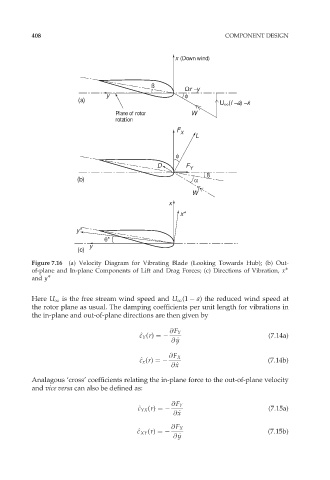
Figure 7.16 (a) Velocity Diagram for Vibrating Blade (Looking Towards Hub); (b) Out-
of-plane and In-plane Components of Lift and Drag Forces; (c) Directions of Vibration, x
and y
Here U 1 is the free stream wind speed and U 1 (1 a) the reduced wind speed at
the rotor plane as usual. The damping coefficients per unit length for vibrations in
the in-plane and out-of-plane directions are then given by
@F Y
^ c c Y (r) ¼ (7:14a)
y
@ _ y
@F X
^ c c x (r) ¼ (7:14b)
x
@ _ x
Analagous ‘cross’ coefficients relating the in-plane force to the out-of-plane velocity
and vice versa can also be defined as:
@F Y
^ c c YX (r) ¼ (7:15a)
x
@ _ x
@F X
^ c c XY (r) ¼ (7:15b)
@ _ y
y