Page 436 - Wind Energy Handbook
P. 436

410                                                     COMPONENT DESIGN

                                 2        V @P9      1            @P9
                         ^ c c Y ¼   P9 þ        ¼        2P9 þ V              (7:21)
                                 2 2
                                          2 2
                                                     2 2
                                Ù r      Ù r @V    Ù r            @V
                                @F Y  @F Y  1 @              1 @P9
                        ^ c c XY ¼   ¼   ¼        (ÙrF Y ) ¼                   (7:22)
                                 x
                                @ _ x  @V   Ùr @V           Ùr @V

                              1           @F X
                        ^ c c XY ¼  2F X   V                                   (7:23)
                              Ùr          @V
                                @F X  @F X
                         ^ c c X ¼   ¼                                         (7:24)
                                @ _ x  @V
                                 x
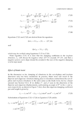
          Equations (7.21) and (7.23) are derived from the equations
                                 Ùr^ c Y þ V^ c YX ¼ 2F Y ¼ 2P9=Ùr
                                          c
                                    c
          and

                                                c
                                         c
                                      Ùr^ c XY þ V^ c X ¼ 2F X
          which may be verified using Equations (7.17) to (7.20).
            From Equation (7.21) it is clear that the damping coefficient in the in-plane
          direction, ^ c Y , will always be negative when 2(P9=V) exceeds @P9=@V, and that a
                    c
          negative power curve slope should be avoided if the size of the negative damping
          is to be kept small.


          Effect of blade twist

          In the discussion so far, damping of vibrations in the out-of-plane and in-plane
          directions only has been considered. In practice, blade twist will result in the
          flapwise and edgewise vibrations taking place in directions rotated from the out-of-
          plane and in-plane directions in the same sense as the blade twist, but by a lesser

          amount (see Section 5.8.1). If we define x - and y -axes in the directions of the

          flapwise and edgewise displacements, each making an angle of Ł to the x- and y-
          axes respectively, as shown in Figure 7.16(c), then the edgewise damping coefficient
          per unit length is given by:

                                  2


                                                                    2
                       ^ c c   ¼ ^ c Y cos Ł   (^ c YX þ ^ c XY ) sin Ł cos Ł þ ^ c X sin Ł  (7:25)
                                                               c
                                              c
                             c
                                        c
                        Y
          Substitution of Equations (7.21)–(7.24) in Equation (7.25) yields:

                  2

          ^ c c   ¼ cos Ł  1   2P9 þ V  @P9  þ cos Ł sin Ł    1     @P9  þ 2F X   V  @F X
           Y            2 2
                      Ù r             @V                 Ùr     @V           @V

                    2
                þ sin Ł  @F X                                                  (7:26)
                         @V
   431   432   433   434   435   436   437   438   439   440   441