
Page 437 - Wind Energy Handbook
P. 437
BLADES 411
This expression also gives the flapwise damping coefficient per unit length if Ł is
replaced by Ł þ 908 throughout.
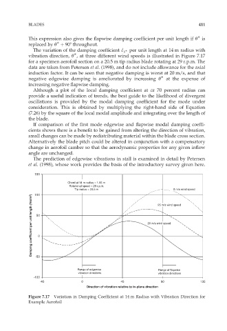
The variation of the damping coefficient ^ c per unit length at 14 m radius with
c
Y
vibration direction, Ł , at three different wind speeds is illustrated in Figure 7.17
for a specimen aerofoil section on a 20.5 m tip radius blade rotating at 29 r.p.m. The
data are taken from Petersen et al. (1998), and do not include allowance for the axial
induction factor. It can be seen that negative damping is worst at 20 m/s, and that
negative edgewise damping is ameliorated by increasing Ł at the expense of
increasing negative flapwise damping.
Although a plot of the local damping coefficient at ca 70 percent radius can
provide a useful indication of trends, the best guide to the likelihood of divergent
oscillations is provided by the modal damping coefficient for the mode under
consideration. This is obtained by multiplying the right-hand side of Equation
(7.26) by the square of the local modal amplitude and integrating over the length of
the blade.
If comparison of the first mode edgewise and flapwise modal damping coeffi-
cients shows there is a benefit to be gained from altering the direction of vibration,
small changes can be made by redistributing material within the blade cross section.
Alternatively the blade pitch could be altered in conjunction with a compensatory
change in aerofoil camber so that the aerodynamic properties for any given inflow
angle are unchanged.
The prediction of edgewise vibrations in stall is examined in detail by Petersen
et al. (1998), whose work provides the basis of the introductory survey given here.
150
Chord at 14 m radius = 1.06 m
Rotational speed = 29 r.p.m.
8 m/s wind speed
Tip radius = 20.5 m 25 m/s wind speed
100
Damping coefficient per unit length (Ns/m 2 ) 50 0 20 m/s wind speed
-50
Range of edgewise Range of flapwise
vibration directions vibration directions
-100
-45 0 45 90 135
Direction of vibration relative to in-plane direction
Figure 7.17 Variation in Damping Coefficient at 14 m Radius with Vibration Direction for
Example Aerofoil