Page 442 - Wind Energy Handbook
P. 442
416                                                     COMPONENT DESIGN


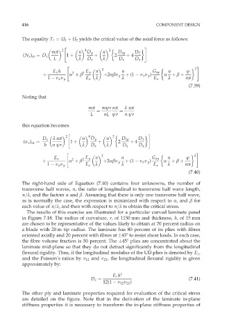
          The equality T 1 ¼ U 1 þ U 2 yields the critical value of the axial force as follows:
                            "                                #
                           2        4
                                              2
                       mð         n  D y    n     D xy   D T
           (N x ) cr ¼ D x   1 þ        þ        2    þ 4
                       L          º  D x    º     D x    D x
                             "                                                     #
                       E x h   2   2  E y  n  2     n           G xy   n       ł  2
                   þ          Æ þ â         þ2Æâı y  þ (1   ı x ı y )  Æ  þ â þ
                     1   ı x ı y     E x  º         º            E x   º      nð
                                                                               (7:39)

          Noting that
                                      mð   młr nð    º nð
                                         ¼         ¼
                                       L    nL łr    n łr

          this equation becomes
                             "                                 #
                             2        4
                                                2
                   D x  º nð       n   D y   n      D xy   D T
           (ó x ) cr ¼        1 þ         þ       2    þ 4
                   h   n łr        º   D x   º      D x    D x
                             "                                                     #
                                           2                                      2
                       E x     2   2  E y  n       n            G xy   n      ł
                   þ          Æ þ â         þ2Æâı y  þ (1   ı x ı y )  Æ  þ â þ
                     1   ı x ı y     E x  º        º             E x   º      nð
                                                                               (7:40)
          The right-hand side of Equation (7.40) contains four unknowns, the number of
          transverse half waves, n, the ratio of longitudinal to transverse half wave length,
          n=º, and the factors Æ and â. Assuming that there is only one transverse half wave,
          as is normally the case, the expression is minimized with respect to Æ, and â for
          each value of n=º, and then with respect to n=º to obtain the critical stress.
            The results of this exercise are illustrated for a particular curved laminate panel
          in Figure 7.18. The radius of curvature, r, of 1150 mm and thickness, h,of 15 mm
          are chosen to be representative of the values likely to obtain at 70 percent radius on
          a blade with 20 m tip radius. The laminate has 80 percent of its plies with fibres
          oriented axially and 20 percent with fibres at  458 to resist shear loads. In each case,
          the fibre volume fraction is 50 percent. The  458 plies are concentrated about the
          laminate mid-plane so that they do not detract significantly from the longitudinal
          flexural rigidity. Thus, if the longitudinal modulus of the UD plies is denoted by E 1 ,
          and the Poisson’s ratios by ı 12 and ı 21 , the longitudinal flexural rigidity is given
          approximately by:

                                                E 1 h 3
                                       D x ¼                                   (7:41)
                                            12(1   ı 12 ı 21 )
          The other ply and laminate properties required for evaluation of the critical stress
          are detailed on the figure. Note that in the derivation of the laminate in-plane
          stiffness properties it is necessary to transform the in-plane stiffness properties of

