Page 447 - Wind Energy Handbook
P. 447
ROTOR HUB                                                              421


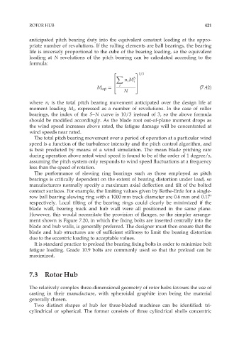
             anticipated pitch bearing duty into the equivalent constant loading at the appro-
             priate number of revolutions. If the rolling elements are ball bearings, the bearing
             life is inversely proportional to the cube of the bearing loading, so the equivalent
             loading at N revolutions of the pitch bearing can be calculated according to the
             formula:
                                               2        3 1=3
                                                X
                                               6    n i M 3 i 7
                                               4        5
                                         M eqt ¼  i                               (7:42)
                                                    N

             where n i is the total pitch bearing movement anticipated over the design life at
             moment loading M i , expressed as a number of revolutions. In the case of roller
             bearings, the index of the S–N curve is 10/3 instead of 3, so the above formula
             should be modified accordingly. As the blade root out-of-plane moment drops as
             the wind speed increases above rated, the fatigue damage will be concentrated at
             wind speeds near rated.
               The total pitch bearing movement over a period of operation at a particular wind
             speed is a function of the turbulence intensity and the pitch control algorithm, and
             is best predicted by means of a wind simulation. The mean blade pitching rate
             during operation above rated wind speed is found to be of the order of 1 degree/s,
             assuming the pitch system only responds to wind speed fluctuations at a frequency
             less than the speed of rotation.
               The performance of slewing ring bearings such as those employed as pitch
             bearings is critically dependent on the extent of bearing distortion under load, so
             manufacturers normally specify a maximum axial deflection and tilt of the bolted
             contact surfaces. For example, the limiting values given by Rothe-Erde for a single-
             row ball bearing slewing ring with a 1000 mm track diameter are 0.6 mm and 0.178
             respectively. Local tilting of the bearing rings could clearly be minimized if the
             blade wall, bearing track and hub wall were all positioned in the same plane.
             However, this would necessitate the provision of flanges, so the simpler arrange-
             ment shown is Figure 7.20, in which the fixing bolts are inserted centrally into the
             blade and hub walls, is generally preferred. The designer must then ensure that the
             blade and hub structures are of sufficient stiffness to limit the bearing distortion
             due to the eccentric loading to acceptable values.
               It is standard practice to preload the bearing fixing bolts in order to minimize bolt
             fatigue loading. Grade 10.9 bolts are commonly used so that the preload can be
             maximized.


             7.3   Rotor Hub

             The relatively complex three-dimensional geometry of rotor hubs favours the use of
             casting in their manufacture, with spheroidal graphite iron being the material
             generally chosen.
               Two distinct shapes of hub for three-bladed machines can be identified: tri-
             cylindrical or spherical. The former consists of three cylindrical shells concentric

