
Page 451 - Wind Energy Handbook
P. 451
GEARBOX 425
of between about 1:31 and 1:88 are therefore required. Normally these large step-
ups are achieved by three separate stages with ratios of between 1:3 and 1:5 each.
The design of industrial fixed ratio gearboxes is a large subject in itself and well
beyond the scope of the present work. However, it is important to recognize that
the use of such gearboxes in wind turbines is a special application, because of the
unusual environment and load characteristics, and the sections which follow focus
on these aspects. Sections 7.4.2 to 7.4.6 consider variable loading, including drive
train dynamics and the impact of emergency braking loads, and examine how gear
fatigue design is adapted to take account of it. The relative benefits of parallel and
epicyclic shaft arrangements are discussed in Section 7.4.7, while subsequent
sections deal with noise reduction measures, and lubrication and cooling. A useful
reference is the American Gear Manufacturers Association Information Sheet (1996)
which covers the special requirements of wind turbine gearboxes in some detail.
7.4.2 Variable loads during operation
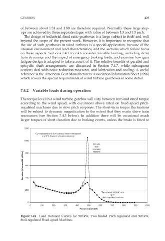
The torque level in a wind turbine gearbox will vary between zero and rated torque
according to the wind speed, with excursions above rated on fixed-speed pitch-
regulated machines due to slow pitch response. The short-term torque fluctuations
will be subject to dynamic magnification to the extent that they excite drive train
resonances (see Section 7.4.3 below). In addition there will be occasional much
larger torques of short duration due to braking events, unless the brake is fitted to
1200
Curves based on 8.5 m/s annual mean wind speed
and IEC Class A turbulence intensity
1000
500 kW,
stall-
regulated
Duration (h/annum/20 kW bin) 600
machine
800
400
200
Two-bladed 500 kW, 40.4
r.p.m.
pitch-regulated machine
0
0 100 200 300 400 500 600 700 800 900 1000
Power output (kW)
Figure 7.24 Load Duration Curves for 500 kW, Two-bladed Pitch-regulated and 500 kW,
Stall-regulated Fixed-speed Machines