
Page 456 - Wind Energy Handbook
P. 456
430 COMPONENT DESIGN
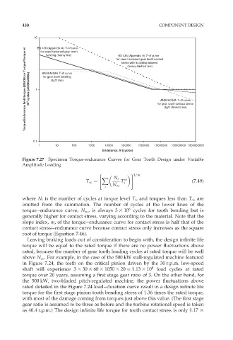
10 BS 436 (Appendix A) T–N curve for case hardened gear tooth contact
Torque/Endurance limit torque (BS436) or Torque/Torque at 10 7 cycles (ANSI/AGMA) 1 ANSI/AGMA T–N curve (heavy dashed line) for gear tooth contact stress
for case hardened gear tooth
bending (heavy line)
BS 436 (Appendix A) T–N curve
stress with no pitting allowed
for gear tooth bending
(light line)
ANSI/AGMA T–N curve
(light dashed line)
0.1
1 10 100 1000 10000 100000 1000000 10000000 100000000 1000000000
Endurance, N (cycles)
Figure 7.27 Specimen Torque-endurance Curves for Gear Tooth Design under Variable
Amplitude Loading
" # 1=m
X N i
T 1 ¼ T m (7:49)
i
N 1
i
where N i is the number of cycles at torque level T i , and torques less than T 1 are
omitted from the summation. The number of cycles at the lower knee of the
6
torque–endurance curve, N 1 , is always 3 3 10 cycles for tooth bending but is
generally higher for contact stress, varying according to the material. Note that the
slope index, m, of the torque–endurance curve for contact stress is half that of the
contact stress–endurance curve because contact stress only increases as the square
root of torque (Equation 7.46).
Leaving braking loads out of consideration to begin with, the design infinite life
torque will be equal to the rated torque if there are no power fluctuations above
rated, because the number of gear tooth loading cycles at rated torque will be well
above N 1 . For example, in the case of the 500 kW stall-regulated machine featured
in Figure 7.24, the teeth on the critical pinion driven by the 30 r.p.m. low-speed
shaft will experience 3 3 30 3 60 3 1050 3 20 ¼ 1:13 3 10 8 load cycles at rated
torque over 20 years, assuming a first stage gear ratio of 3. On the other hand, for
the 500 kW, two-bladed pitch-regulated machine, the power fluctuations above
rated detailed in the Figure 7.24 load–duration curve result in a design infinite life
torque for the first stage pinion tooth bending stress of 1.36 times the rated torque,
with most of the damage coming from torques just above this value. (The first stage
gear ratio is assumed to be three as before and the turbine rotational speed is taken
as 40.4 r.p.m.) The design infinite life torque for tooth contact stress is only 1:17 3