
Page 454 - Wind Energy Handbook
P. 454
428 COMPONENT DESIGN
4
HSS
stops
40
Aero tips
deploy
Shaft torsion (kNm) Normal 2 3 5
20
1
0 operation
Torque reversals
Brake torque
and teeth impacts
rising
Generator
off-line
20
0 5 10 15 20
Time (s)
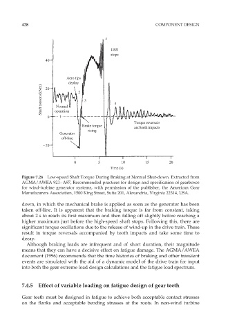
Figure 7.26 Low-speed Shaft Torque During Braking at Normal Shut-down. Extracted from
AGMA/AWEA 921–A97, Recommended practices for design and specification of gearboxes
for wind-turbine generator systems, with permission of the publisher, the American Gear
Manufacurers Association, 1500 King Street, Suite 201, Alexandria, Virginia 22314, USA.
down, in which the mechanical brake is applied as soon as the generator has been
taken off-line. It is apparent that the braking torque is far from constant, taking
about 2 s to reach its first maximum and then falling off slightly before reaching a
higher maximum just before the high-speed shaft stops. Following this, there are
significant torque oscillations due to the release of wind-up in the drive train. These
result in torque reversals accompanied by tooth impacts and take some time to
decay.
Although braking loads are infrequent and of short duration, their magnitude
means that they can have a decisive effect on fatigue damage. The AGMA/AWEA
document (1996) recommends that the time histories of braking and other transient
events are simulated with the aid of a dynamic model of the drive train for input
into both the gear extreme load design calculations and the fatigue load spectrum.
7.4.5 Effect of variable loading on fatigue design of gear teeth
Gear teeth must be designed in fatigue to achieve both acceptable contact stresses
on the flanks and acceptable bending stresses at the roots. In non-wind turbine