
Page 449 - Wind Energy Handbook
P. 449
ROTOR HUB 423
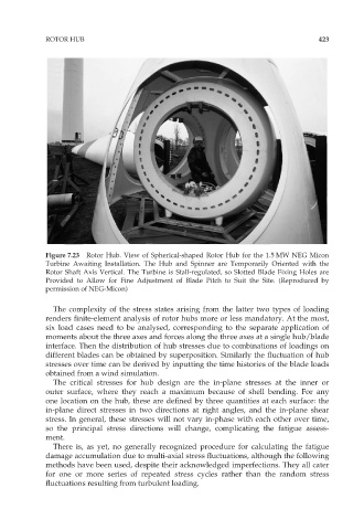
Figure 7.23 Rotor Hub. View of Spherical-shaped Rotor Hub for the 1.5 MW NEG Micon
Turbine Awaiting Installation. The Hub and Spinner are Temporarily Oriented with the
Rotor Shaft Axis Vertical. The Turbine is Stall-regulated, so Slotted Blade Fixing Holes are
Provided to Allow for Fine Adjustment of Blade Pitch to Suit the Site. (Reproduced by
permission of NEG-Micon)
The complexity of the stress states arising from the latter two types of loading
renders finite-element analysis of rotor hubs more or less mandatory. At the most,
six load cases need to be analysed, corresponding to the separate application of
moments about the three axes and forces along the three axes at a single hub/blade
interface. Then the distribution of hub stresses due to combinations of loadings on
different blades can be obtained by superposition. Similarly the fluctuation of hub
stresses over time can be derived by inputting the time histories of the blade loads
obtained from a wind simulation.
The critical stresses for hub design are the in-plane stresses at the inner or
outer surface, where they reach a maximum because of shell bending. For any
one location on the hub, these are defined by three quantities at each surface: the
in-plane direct stresses in two directions at right angles, and the in-plane shear
stress. In general, these stresses will not vary in-phase with each other over time,
so the principal stress directions will change, complicating the fatigue assess-
ment.
There is, as yet, no generally recognized procedure for calculating the fatigue
damage accumulation due to multi-axial stress fluctuations, although the following
methods have been used, despite their acknowledged imperfections. They all cater
for one or more series of repeated stress cycles rather than the random stress
fluctuations resulting from turbulent loading.