
Page 448 - Wind Energy Handbook
P. 448
422 COMPONENT DESIGN
with the blade axes, which flare into each other where they meet, while the latter
consists simply of a spherical shell with cut-outs at the three-blade mounting
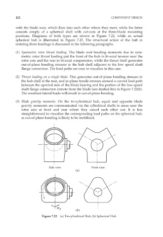
positions. Diagrams of both types are shown in Figure 7.22, while an actual
spherical hub is illustrated in Figure 7.23. The structural action of the hub in
resisting three loadings is discussed in the following paragraphs.
(1) Symmetric rotor thrust loading. The blade root bending moments due to sym-
metric rotor thrust loading put the front of the hub in bi-axial tension near the
rotor axis and the rear in bi-axial compression, while the thrust itself generates
out-of-plane bending stresses in the hub shell adjacent to the low speed shaft
flange connection. The load paths are easy to visualize in this case.
(2) Thrust loading on a single blade. This generates out-of-plane bending stresses in
the hub shell at the rear, and in-plane tensile stresses around a curved load path
between the upwind side of the blade bearing and the portion of the low-speed
shaft flange connection remote from the blade (see dashed line in Figure 7.22(b).
The resultant lateral loads will result in out-of-plane bending.
(3) Blade gravity moments. On the tri-cylindrical hub, equal and opposite blade
gravity moments are communicated via the cylindrical shells to areas near the
rotor axis at front and rear where they cancel each other out. It is less
straightforward to visualize the corresponding load paths on the spherical hub,
as out-of-plane bending is likely to be mobilized.
Side view Front view
(a)
M Y (b)
Figure 7.22 (a) Tri-cylindrical Hub; (b) Spherical Hub