
Page 443 - Wind Energy Handbook
P. 443
BLADES 417
400
Laminate structure:
80% of plies with axial fibres (outer plies);
350 20% of plies with fibres at 45 (inner plies);
Critical stress for 50% fibre volume fraction
isotropic panel with E = 37.7 GPa
300 Ply properties:
E 1 = 37.7 GPa, E 2 = 11.3 GPa,
ν 12 = 0.29, ν 21 = 0.087, G 12 = 3.3 GPa
Critical stress (MPa) 200 Laminate critical stress Laminate critical stress with one transverse half wave (n = 1)
250
Laminate properties:
E x = 33.6 GPa, E y = 12.4 Gpa
vx = 0.38, vy = 0.14, G xy = 4.8 GPa
D y /D x = 0.30, D xy /D x = 0.087, D t /D x = 0.086
with two transverse
half waves (n = 2)
150
100
In-plane contribution to critical stress (n = 1)
Flexural contribn to critical stress (n = 1)
50
0
0 0.2 0.4 0.6 0.8 1 1.2 1.4
Angle subtended by panel (radians)
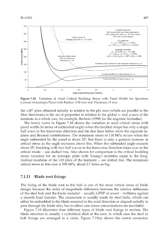
Figure 7.18 Variation of Axial Critical Buckling Stress with Panel Width for Specimen
Curved Anisotropic Panel with Radius 1150 mm and Thickness 15 mm
the 458 plies obtained initially in relation to the ply axes (which are parallel to the
fibre directions) to the set of properties in relation to the global x- and y-axes of the
laminate as a whole (see, for example, Barbero (1998) for the requisite formulae).
The heavy curve in Figure 7.18 shows the variation in axial critical stress with
panel width (in terms of subtended angle) when the buckled shape has only a single
half wave in the transverse direction and the fine lines below show the separate in-
plane and flexural contributions. The minimum stress of 110 MPa occurs when the
angle subtended by the panel is about 208, but there is only a gradual increase in
critical stress as the angle increases above this. When the subtended angle exceeds
about 358, buckling with two half waves in the transverse direction takes over as the
critical mode – see dashed line. Also shown for comparison is the critical buckling
stress variation for an isotropic plate with Young’s modulus equal to the long-
itudinal modulus of the UD plies of the laminate – see dotted line. The minimum
critical stress in this case is 298 MPa, about 2.7 times as big.
7.1.11 Blade root fixings
The fixing of the blade root to the hub is one of the most critical areas of blade
design, because the order of magnitude difference between the relative stiffnesses
of the steel hub and the blade material – usually GFRP or wood – militates against
a smooth load transfer. The connection is usually made by steel bolts, which can
either be embedded in the blade material in the axial direction or aligned radially to
pass through the blade skin, but in either case stress concentrations are inevitable.
Figure 7.19 illustrates four different types of blade root fixings in section. The
blade structure is usually a cylindrical shell at the root, in which case the stud or
bolt fixings are arranged in a circle. Figure 7.19(a) shows the carrot connector,