
Page 445 - Wind Energy Handbook
P. 445
PITCH BEARINGS 419
The stress distributions calculated for blade root fixings are subject to significant
levels of uncertainty, so it is normal to conduct both static and fatigue tests on them
to verify the suitability of the design. Static pull-out failures of carrot connectors
occur as a result of shearing of the wood surrounding the grout, but fatigue failures
can also occur in the connector itself or the grout. However, SGI studs subjected to
R ¼ 0:1 fatigue loading at over 60 percent of the UTS have survived for approxi-
6
mately 10 cycles.
Mayer (1996) records the results of fatigue tests on the other blade root fixings
featured in Figure 7.19, but in no case did failure occur as a result of fatigue of the
GFRP in the region of the root fixing. In the case of the T-bolt fixing arrangement,
failure occurred in the studs rather than in the GRP. The pin-hole flange specimens
developed fatigue cracks in the GFRP in areas remote from the root fixings and the
trumpet flange specimens developed cracks in the flanges themselves.
7.2 Pitch Bearings
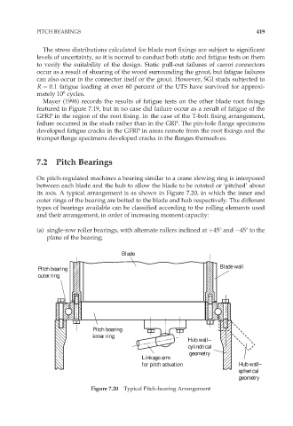
On pitch-regulated machines a bearing similar to a crane slewing ring is interposed
between each blade and the hub to allow the blade to be rotated or ‘pitched’ about
its axis. A typical arrangement is as shown in Figure 7.20, in which the inner and
outer rings of the bearing are bolted to the blade and hub respectively. The different
types of bearings available can be classified according to the rolling elements used
and their arrangement, in order of increasing moment capacity:
(a) single-row roller bearings, with alternate rollers inclined at þ458 and 458 to the
plane of the bearing;
Blade
Blade wall
Pitch bearing
outer ring
Pitch bearing
inner ring
Hub wall–
cylindrical
geometry
Linkage arm
for pitch actuation Hub wall–
spherical
geometry
Figure 7.20 Typical Pitch-bearing Arrangement