
Page 446 - Wind Energy Handbook
P. 446
420 COMPONENT DESIGN
(b) single-row ball bearings,
(c) double-row ball bearings;
(d) three-row roller bearings.
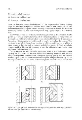
These are shown in cross section in Figure 7.21. The single-row ball bearing slewing
rings are normally designed to transmit axial loads in both directions and are
therefore known as four point contact bearings. Low contact stresses are achieved
by making the radii on each side of the grooves only slightly larger than that of the
balls.
At low wind speeds, the cyclic in-plane bending moment at the blade root due to
gravity is of similar magnitude to the out-of-plane moment due to blade thrust, so
bearing loads will alternate in direction over portions of the bearing circumference.
Accordingly it is desirable to avoid the risk of play by preloading the bearing. This
can be achieved relatively easily on bearings in which one of the rings is split on a
plane normal to the axis, such as types (c) and (d), but is more difficult when both
rings are solid. In this case it is necessary to force the rolling elements into the races
one by one during manufacture.
The bearing selected for a particular application needs to have sufficient moment
capacity to both resist the extreme blade root bending moments and provide
adequate fatigue life. Manufacturers’ catalogues typically specify both the extreme
moment capacity and the steady moment loading that will give a life of, say, 30 000
bearing revolutions, so the wind turbine designer’s chief task is to convert the
(a) (b)
(c) (d)
Figure 7.21 (a) Single-row Crossed Roller Bearings; (b) Single-row Ball Bearings; (c) Double-
row Ball Bearings; (d) Three-row Roller Bearings