
Page 444 - Wind Energy Handbook
P. 444
418 COMPONENT DESIGN
Blade Blade
Cylindrical nut
Carbon epoxy grout
(a) (b)
Blade Blade
(c) (d)
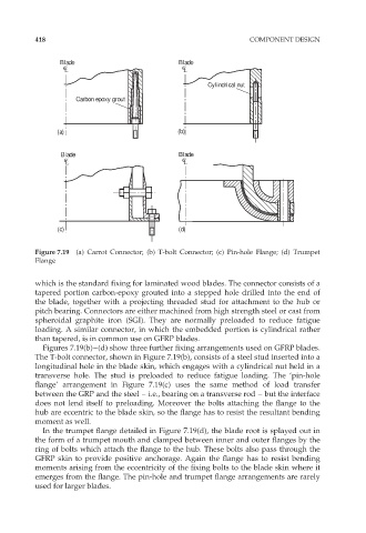
Figure 7.19 (a) Carrot Connector; (b) T-bolt Connector; (c) Pin-hole Flange; (d) Trumpet
Flange
which is the standard fixing for laminated wood blades. The connector consists of a
tapered portion carbon-epoxy grouted into a stepped hole drilled into the end of
the blade, together with a projecting threaded stud for attachment to the hub or
pitch bearing. Connectors are either machined from high strength steel or cast from
spheroidal graphite iron (SGI). They are normally preloaded to reduce fatigue
loading. A similar connector, in which the embedded portion is cylindrical rather
than tapered, is in common use on GFRP blades.
Figures 7.19(b)–(d) show three further fixing arrangements used on GFRP blades.
The T-bolt connector, shown in Figure 7.19(b), consists of a steel stud inserted into a
longitudinal hole in the blade skin, which engages with a cylindrical nut held in a
transverse hole. The stud is preloaded to reduce fatigue loading. The ‘pin-hole
flange’ arrangement in Figure 7.19(c) uses the same method of load transfer
between the GRP and the steel – i.e., bearing on a transverse rod – but the interface
does not lend itself to preloading. Moreover the bolts attaching the flange to the
hub are eccentric to the blade skin, so the flange has to resist the resultant bending
moment as well.
In the trumpet flange detailed in Figure 7.19(d), the blade root is splayed out in
the form of a trumpet mouth and clamped between inner and outer flanges by the
ring of bolts which attach the flange to the hub. These bolts also pass through the
GFRP skin to provide positive anchorage. Again the flange has to resist bending
moments arising from the eccentricity of the fixing bolts to the blade skin where it
emerges from the flange. The pin-hole and trumpet flange arrangements are rarely
used for larger blades.