Page 435 - Wind Energy Handbook
P. 435

BLADES                                                                 409


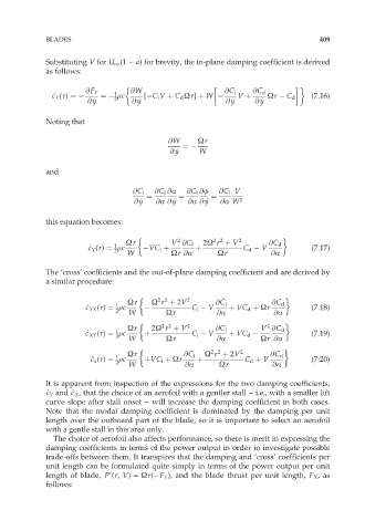
             Substituting V for U 1 (1   a) for brevity, the in-plane damping coefficient is derived
             as follows:

                       @F Y    1   @W                       @C l   @C d
               ^ c c Y (r) ¼   ¼  rc   [ C l V þ C d Ùr] þ W    V þ    Ùr   C d   (7:16)
                               2
                                                             y
                                                                     y
                         y
                                     y
                        @ _ y      @ _ y                    @ _ y   @ _ y
             Noting that
                                             @W      Ùr
                                                 ¼
                                             @ _ y   W
                                               y
             and

                                    @C l  @C l @Æ  @C l @ö  @C l V
                                       ¼        ¼       ¼
                                    @ _ y  @Æ @ _ y  @Æ @ _ y  @Æ W 2
                                     y
                                              y
                                                      y
             this equation becomes:

                                                         2 2
                                               2
                                  Ùr          V @C l  2Ù r þ V 2       @C d
                               1
                        ^ c c Y (r) ¼ rc   VC l þ   þ            C d   V          (7:17)
                               2  W           Ùr @Æ       Ùr            @Æ
             The ‘cross’ coefficients and the out-of-plane damping coefficient and are derived by
             a similar procedure:

                                          2 2
                                  Ùr     Ù r þ 2V 2      @C l           @C d
                               1
                       ^ c c YX (r) ¼ rc           C l   V   þ VC d þ Ùr          (7:18)
                               2   W        Ùr            @Æ            @Æ

                                           2 2
                                                                       2
                                  Ùr     2Ù r þ V 2      @C l        V @C d
                               1
                       ^ c c XY (r) ¼ rc  þ        C l   V   þ VC d               (7:19)
                               2   W        Ùr            @Æ         Ùr @Æ

                                                        2 2
                                  Ùr             @C l  Ù r þ 2V 2      @C d
                               1
                         ^ c c x (r) ¼ rc  þVC l þ Ùr  þ         C d þ V          (7:20)
                               2   W             @Æ       Ùr            @Æ
             It is apparent from inspection of the expressions for the two damping coefficients,
                    c
             ^ c c Y and ^ c X , that the choice of an aerofoil with a gentler stall – i.e., with a smaller lift
             curve slope after stall onset – will increase the damping coefficient in both cases.
             Note that the modal damping coefficient is dominated by the damping per unit
             length over the outboard part of the blade, so it is important to select an aerofoil
             with a gentle stall in this area only.
               The choice of aerofoil also affects performance, so there is merit in expressing the
             damping coefficients in terms of the power output in order to investigate possible
             trade-offs between them. It transpires that the damping and ‘cross’ coefficients per
             unit length can be formulated quite simply in terms of the power output per unit
             length of blade, P9(r, V) ¼ Ùr( F Y ), and the blade thrust per unit length, F X ,as
             follows:
   430   431   432   433   434   435   436   437   438   439   440