
Page 410 - Characterization and Properties of Petroleum Fractions - M.R. Riazi
P. 410
QC: IML/FFX
P2: IML/FFX
P1: IML/FFX
AT029-09
June 22, 2007
AT029-Manual
390 CHARACTERIZATION AND PROPERTIES OF PETROLEUM FRACTIONS
300 AT029-Manual-v7.cls T1: IML 14:25 and at 285 K, y i /K i VS = 1.073. Finally at T = 285.3877 K,
VS
29 wt% 16 wt% 0 wt% y i /K i = 1.00000, which is the correct answer. Thus the
◦
MEOH HFT for this gas at 30 bar is 285.4 K or 12.2 C. At this
250 Experimental
temperature from Eq. (9.45), K 1 = 2.222, K 2 = 0.7603, and
Calculated K 3 = 0.113. Composition of hydrocarbons in a water-free
Pressure, atm__ 150 base hydrate is calculated as x = y i K i , which gives x =
200
S
S
VS
i
1
0.36, x = 0.197, and x = 0.443. (b) At 414 bars Eq. (9.46)
S
S
2
3
with coefficients in Table 9.12 should be used. At this pres-
sure HFT is calculated as 303.2 K or HFT = 30 C. (c) To de-
◦
100
crease HFT at 30 bars an inhibitor solution that can cause
depression of T = 12.2 − 5 = 7.2 C is needed. Rearrang-
◦
50 ing Eq. (9.47): wt% = 100[M T/(A + M T)], where wt% is
the weight percent of inhibitor in aqueous solution. From
0 Table 9.13 for methanol, A = 1297.2 and M = 32. Thus with
260 270 280 290 300 T = 7.2, wt% = 15.1. Since calculated wt% of methanol
Temperature, K is less than 20% use of Eq. (9.47) is justified. For pressure
of 414 bars Eq. (9.48) should be used for methanol where
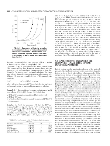
FIG. 9.24—Depression of hydrate formation
temperature in methane by methanol-calculated upon rearrangement one can get x MeOH = 1 − exp(− T/72).
◦
versus measured values. Lines represent coex- At T = 30 − 5 = 25 C we get x MeOH = 0.293. For an aque-
istence curves for methane, hydrate, and aque- ous solution (M H 2 O = 18) and from Eq. (1.15), the wt% of
ous solutions of MeOH. Taken with permission methanol (M = 32) can be calculated as: wt% = 42.4.
from Ref. [55].
9.6 APPLICATIONS: ENHANCED OIL
for some common inhibitors are given in Table 9.13. Values RECOVERY—EVALUATION OF GAS
of A are corrected values as given in Ref. [14]. INJECTION PROJECTS
Equation (9.47) is recommended for sweet natural gases
(H 2 S content of less than 4 ppm on volume basis, also see In this section another application of some of the methods
Section 1.7.15) with inhibitor concentrations of less than presented in this book is shown for the evaluation of gas in-
20 mol%. For concentrated methanol solutions, like those jection projects. Gas is injected into oil reservoirs for differ-
used to free a plugged-up tubing string in a high-pressure well, ent purposes: storage of gas, maintenance of reservoir pres-
Whitson [1] suggests a modified form of Hammerschmidt sure, and enhanced recovery of hydrocarbons. In the last case,
equation:
understanding and modeling of the diffusion process is of
(9.48) T =−72 ln (1 − x MeOH) importance to the planning and evaluation of gas injection
projects. Gases such as natural gas, methane, ethane, lique-
◦
where T is the decrease in HFT in C (or in kelvin) and x MeOH fied petroleum gas (LPG), or carbon dioxide are used as misci-
is the mole fraction of methanol in the aqueous solution. ble gas flooding in EOR techniques. Upon injection of a gas, it
is dissolved into oil under reservoir conditions and increases
Example 9.4—Composition of a natural gas in terms of mol% the mobility of oil due to decrease in its viscosity. To reach a
is as follows: 85% C 1 , 10% C 2 , and 5% C 3 . Calculate
certain mobility limit a certain gas concentration is required.
a. HFT at 30 bars and composition of hydrate formed. For planning and evaluation of such projects, it is desired to
b. HFT at 414 bars. predict the amount of gas and duration of its injection in an
c. wt% of methanol solution needed to decrease HFT to 5 C oil reservoir. In such calculations, properties such as density,
◦
for each case. viscosity, diffusivity and phase behavior of oil and gas are
needed. The purpose of this section is to show how to apply
Solution—(a) At 30 bar pressure (<70 bar) the HFT can methods presented in this book to obtain desired information
be calculated from Eqs. (9.44) and (9.45) by trial-and-error for such projects. This application is shown through modeling
method. Assuming HFT of 280 K, the sum in Eq. (9.44) of fractured reservoirs for a North Sea reservoir for the study
is y i /K VS = 2.848 since it is greater than 1, temperature of nitrogen injection. Laboratory experimental data are used
i
should be increased in order to decrease K VS values. At T = to evaluate model predictions as discussed by Riazi et al. [56].
300 K, y i /K i VS = 0.308;, at T = 290 K, i y i /K i VS = 0.504; An idealized matrix–fracture system is shown in Fig. 9.25,
where matrix blocks are assumed to be rectangular cubes. Di-
mensions of matrix blocks may vary from 30 to 300 cm, and
TABLE 9.13—Constants in Eq. (9.47) for hydrate formation the thickness of fractures is about 10 –10 −4 cm. When a gas
−2
inhibitors. is injected into a fractured reservoir, the gas flows through
Hydrate formation inhibitor Formula M A the fracture channels in horizontal and vertical directions.
Methanol CH 3 OH 32 1297.2
Ethanol C 2 H 5 OH 46 1297.2 Therefore, all surfaces of a matrix block come into contact
Ethylene glycol C 2 H 6 O 2 62 1500 with the surrounding gas in the fracture. The injected gas
Diethylene glycol C 4 H 10 O 3 106 2222.2 comes into contact with oil in the matrix block at the matrix–
Triethylene glycol C 6 H 14 O 4 150 3000 fracture interface. The gas begins to diffuse into oil and light
--`,```,`,``````,`,````,```,,-`-`,,`,,`,`,,`---
Copyright ASTM International
Provided by IHS Markit under license with ASTM Licensee=International Dealers Demo/2222333001, User=Anggiansah, Erick
No reproduction or networking permitted without license from IHS Not for Resale, 08/26/2021 21:56:35 MDT