
Page 131 - Mechanical Behavior of Materials
P. 131
132 Chapter 4 Mechanical Testing: Tension Test and Other Basic Tests
σ σ
x
x
L
i
ΔL ΔL
L i
d L i
i
d min
ΔL
0
(a) ε
x
(b)
0
ε
(c) x
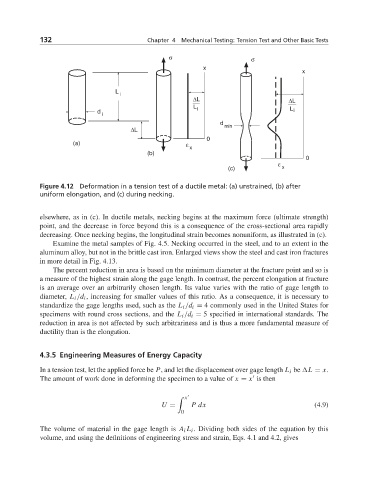
Figure 4.12 Deformation in a tension test of a ductile metal: (a) unstrained, (b) after
uniform elongation, and (c) during necking.
elsewhere, as in (c). In ductile metals, necking begins at the maximum force (ultimate strength)
point, and the decrease in force beyond this is a consequence of the cross-sectional area rapidly
decreasing. Once necking begins, the longitudinal strain becomes nonuniform, as illustrated in (c).
Examine the metal samples of Fig. 4.5. Necking occurred in the steel, and to an extent in the
aluminum alloy, but not in the brittle cast iron. Enlarged views show the steel and cast iron fractures
in more detail in Fig. 4.13.
The percent reduction in area is based on the minimum diameter at the fracture point and so is
a measure of the highest strain along the gage length. In contrast, the percent elongation at fracture
is an average over an arbitrarily chosen length. Its value varies with the ratio of gage length to
diameter, L i /d i , increasing for smaller values of this ratio. As a consequence, it is necessary to
standardize the gage lengths used, such as the L i /d i = 4 commonly used in the United States for
specimens with round cross sections, and the L i /d i = 5 specified in international standards. The
reduction in area is not affected by such arbitrariness and is thus a more fundamental measure of
ductility than is the elongation.
4.3.5 Engineering Measures of Energy Capacity
In a tension test, let the applied force be P, and let the displacement over gage length L i be L = x.
The amount of work done in deforming the specimen to a value of x = x is then
x
U = Pdx (4.9)
0
The volume of material in the gage length is A i L i . Dividing both sides of the equation by this
volume, and using the definitions of engineering stress and strain, Eqs. 4.1 and 4.2, gives