
Page 279 - Mechanical Behavior of Materials
P. 279
280 Chapter 7 Yielding and Fracture under Combined Stresses
σ σ
(a) 2 (b) 2
A σ u B σ
σ
2 = u
D
N
fracture
D
σ σ
−σ u 0 σ u 1 0 1
(σ , σ )
1 2
σ = – σ
−σ C 2 u
u
σ 1 = – σ u σ 1 = σ u
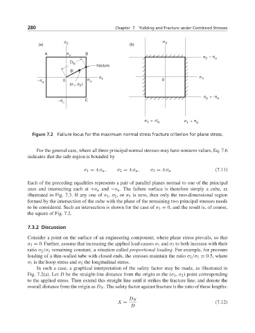
Figure 7.2 Failure locus for the maximum normal stress fracture criterion for plane stress.
For the general case, where all three principal normal stresses may have nonzero values, Eq. 7.6
indicates that the safe region is bounded by
σ 1 =±σ u , σ 2 =±σ u , σ 3 =±σ u (7.11)
Each of the preceding equalities represents a pair of parallel planes normal to one of the principal
axes and intersecting each at +σ u and −σ u . The failure surface is therefore simply a cube, as
illustrated in Fig. 7.3. If any one of σ 1 , σ 2 ,or σ 3 is zero, then only the two-dimensional region
formed by the intersection of the cube with the plane of the remaining two principal stresses needs
to be considered. Such an intersection is shown for the case of σ 3 = 0, and the result is, of course,
the square of Fig. 7.2.
7.3.2 Discussion
Consider a point on the surface of an engineering component, where plane stress prevails, so that
σ 3 = 0. Further, assume that increasing the applied load causes σ 1 and σ 2 to both increase with their
ratio σ 2 /σ 1 remaining constant, a situation called proportional loading. For example, for pressure
loading of a thin-walled tube with closed ends, the stresses maintain the ratio σ 2 /σ 1 = 0.5, where
σ 1 is the hoop stress and σ 2 the longitudinal stress.
In such a case, a graphical interpretation of the safety factor may be made, as illustrated in
Fig. 7.2(a). Let D be the straight-line distance from the origin to the (σ 1 , σ 2 ) point corresponding
to the applied stress. Then extend this straight line until it strikes the fracture line, and denote the
overall distance from the origin as D N . The safety factor against fracture is the ratio of these lengths:
D N
X = (7.12)
D