
Page 280 - Mechanical Behavior of Materials
P. 280
Section 7.3 Maximum Normal Stress Fracture Criterion 281
σ 3
σ
u
D
N
(σ ,σ ,σ )
1 2 3
D
σ
0 σ u 2
σ = 0
σ 3
u
σ
1
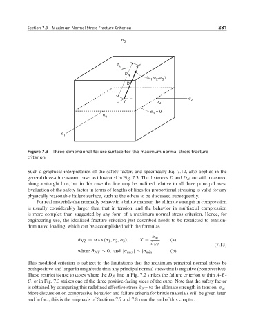
Figure 7.3 Three-dimensional failure surface for the maximum normal stress fracture
criterion.
Such a graphical interpretation of the safety factor, and specifically Eq. 7.12, also applies in the
general three-dimensional case, as illustrated in Fig. 7.3. The distances D and D N are still measured
along a straight line, but in this case the line may be inclined relative to all three principal axes.
Evaluation of the safety factor in terms of lengths of lines for proportional stressing is valid for any
physically reasonable failure surface, such as the others to be discussed subsequently.
For real materials that normally behave in a brittle manner, the ultimate strength in compression
is usually considerably larger than that in tension, and the behavior in multiaxial compression
is more complex than suggested by any form of a maximum normal stress criterion. Hence, for
engineering use, the idealized fracture criterion just described needs to be restricted to tension-
dominated loading, which can be accomplished with the formulas
σ ut
¯ σ NT = MAX(σ 1 ,σ 2 ,σ 3 ), X = (a)
(7.13)
¯ σ NT
where ¯σ NT > 0, and |σ max | > |σ min | (b)
This modified criterion is subject to the limitations that the maximum principal normal stress be
both positive and larger in magnitude than any principal normal stress that is negative (compressive).
These restrict its use to cases where the D N line in Fig. 7.2 strikes the failure criterion within A-B-
C, or in Fig. 7.3 strikes one of the three positive-facing sides of the cube. Note that the safety factor
is obtained by comparing this redefined effective stress ¯σ NT to the ultimate strength in tension, σ ut .
More discussion on compressive behavior and failure criteria for brittle materials will be given later,
and in fact, this is the emphasis of Sections 7.7 and 7.8 near the end of this chapter.