
Page 284 - Mechanical Behavior of Materials
P. 284
Section 7.4 Maximum Shear Stress Yield Criterion 285
σ
3
(a)
σ
2
σ = 0
3
axis
σ
1
σ
3
γ
axis (b)
β
α axis
α = β = γ
(σ , σ , σ ) D'
1 2 3
σ 1 D' S σ 2
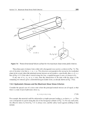
Figure 7.6 Three-dimensional failure surface for the maximum shear stress yield criterion.
These three pairs of planes form a tube with a hexagonal cross section, as shown in Fig. 7.6. The
axis of the tube is the line σ 1 = σ 2 = σ 3 . This direction corresponds to the normal to the octahedral
plane in the octant where the principal normal stresses are all positive—specifically, the α = β = γ
line of Fig. 6.15. If the tube is viewed along this line, a regular hexagon is seen, as shown in (b).
If any one of σ 1 , σ 2 ,or σ 3 is zero, then the intersection of the tube with the plane of the
remaining two stresses gives a distorted hexagon failure locus, as already shown in Fig. 7.5(a).
7.4.3 Hydrostatic Stresses and the Maximum Shear Stress Criterion
Consider the special case of a stress state where the principal normal stresses are all equal, so that
there is a state of pure hydrostatic stress σ h :
σ 1 = σ 2 = σ 3 = σ h (7.26)
For example, the material could be subjected to a simple pressure loading p, so that σ h =−p.This
case corresponds to a point along the axis of the hexagonal cylinder of Fig. 7.6. For any such point,
the effective stress ¯σ S from Eq. 7.21 is always zero, and the safety factor against yielding is thus
infinite.