
Page 286 - Mechanical Behavior of Materials
P. 286
Section 7.4 Maximum Shear Stress Yield Criterion 287
Example 7.3
A solid shaft of diameter d is made of AISI 1020 steel (as rolled) and is subjected to a tensile
axial force of 200 kN and a torque of 1.50 kN·m.
(a) What is the safety factor against yielding if the diameter is 50 mm?
(b) For the situation of (a), what adjusted value of diameter is required to obtain a safety
factor against yielding of 2.0?
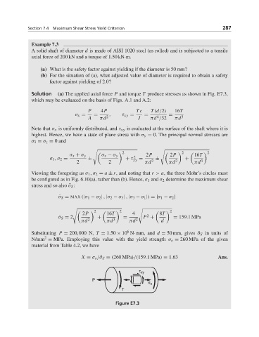
Solution (a) The applied axial force P and torque T produce stresses as shown in Fig. E7.3,
which may be evaluated on the basis of Figs. A.1 and A.2:
P 4P Tc T (d/2) 16T
σ x = = , τ xy = = =
4
A πd 2 J πd /32 πd 3
Note that σ x is uniformly distributed, and τ xy is evaluated at the surface of the shaft where it is
highest. Hence, we have a state of plane stress with σ y = 0. The principal normal stresses are
σ 3 = σ z = 0 and
2 2 2
σ x + σ y σ x − σ y 2 2P 2P 16T
σ 1 ,σ 2 = ± + τ xy = 2 ± 2 + 3
2 2 πd πd πd
Viewing the foregoing as σ 1 ,σ 2 = a ± r, and noting that r > a, the three Mohr’s circles must
be configured as in Fig. 6.10(a), rather than (b). Hence, σ 1 and σ 2 determine the maximum shear
stress and so also ¯σ S :
¯ σ S = MAX (|σ 1 − σ 2 | , |σ 2 − σ 3 | , |σ 3 − σ 1 |) = |σ 1 − σ 2 |
2P 16T 4 8T
2 2 2
2
¯ σ S = 2 + = P + = 159.1MPa
πd 2 πd 3 πd 2 d
6
Substituting P = 200,000 N, T = 1.50 × 10 N·mm, and d = 50 mm, gives ¯σ S in units of
2
N/mm = MPa. Employing this value with the yield strength σ o = 260 MPa of the given
material from Table 4.2, we have
X = σ o / ¯σ S = (260 MPa)/(159.1MPa) = 1.63 Ans.
τ xy
P
σ x
T
Figure E7.3