
Page 291 - Mechanical Behavior of Materials
P. 291
292 Chapter 7 Yielding and Fracture under Combined Stresses
σ
3
σ
o
axis max. shear
oct. shear
σ
o
D' σ o
σ S σ
1 2
D'
H
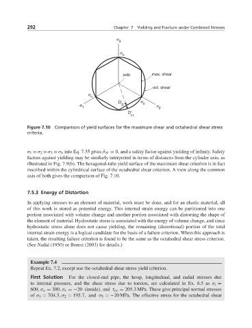
Figure 7.10 Comparison of yield surfaces for the maximum shear and octahedral shear stress
criteria.
σ 1 = σ 2 = σ 3 = σ h into Eq. 7.35 gives ¯σ H = 0, and a safety factor against yielding of infinity. Safety
factors against yielding may be similarly interpreted in terms of distances from the cylinder axis, as
illustrated in Fig. 7.9(b). The hexagonal-tube yield surface of the maximum shear criterion is in fact
inscribed within the cylindrical surface of the octahedral shear criterion. A view along the common
axis of both gives the comparison of Fig. 7.10.
7.5.3 Energy of Distortion
In applying stresses to an element of material, work must be done, and for an elastic material, all
of this work is stored as potential energy. This internal strain energy can be partitioned into one
portion associated with volume change and another portion associated with distorting the shape of
the element of material. Hydrostatic stress is associated with the energy of volume change, and since
hydrostatic stress alone does not cause yielding, the remaining (distortional) portion of the total
internal strain energy is a logical candidate for the basis of a failure criterion. When this approach is
taken, the resulting failure criterion is found to be the same as the octahedral shear stress criterion.
(See Nadai (1950) or Boresi (2003) for details.)
Example 7.4
Repeat Ex. 7.2, except use the octahedral shear stress yield criterion.
First Solution For the closed-end pipe, the hoop, longitudinal, and radial stresses due
to internal pressure, and the shear stress due to torsion, are calculated in Ex. 6.5 as σ t =
600,σ x = 300,σ r =−20 (inside), and τ tx = 205.3 MPa. These give principal normal stresses
of σ 1 = 704.3,σ 2 = 195.7, and σ 3 =−20 MPa. The effective stress for the octahedral shear