
Page 290 - Mechanical Behavior of Materials
P. 290
Section 7.5 Octahedral Shear Stress Yield Criterion 291
σ
3
(a)
σ
2
σ = 0
3
axis
σ
1
σ
γ 3
axis
β (b)
α
α = β = γ
axis
(σ ,σ ,σ ) D'
12 3
σ
1 D' σ
H 2
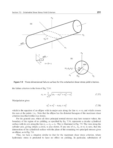
Figure 7.9 Three-dimensional failure surface for the octahedral shear stress yield criterion.
the failure criterion in the form of Eq. 7.34:
1 2 2 2
σ o = √ (σ 1 − σ 2 ) + σ + σ 1 (7.37)
2
2
Manipulation gives
2 2 2
σ = σ − σ 1 σ 2 + σ 2 (7.38)
o
1
which is the equation of an ellipse with its major axis along the line σ 1 = σ 2 and which crosses
the axes at the points ±σ o . Note that the ellipse has the distorted hexagon of the maximum shear
criterion inscribed within it as shown.
For the general case, where all three principal normal stresses may have nonzero values, the
boundary of the region of no yielding, as specified by Eq. 7.34, represents a circular cylindrical
surface with its axis along the line σ 1 = σ 2 = σ 3 . This is illustrated in Fig. 7.9. The view along the
cylinder axis, giving simply a circle, is also shown. If any one of σ 1 , σ 2 ,or σ 3 is zero, then the
intersection of the cylindrical surface with the plane of the remaining two principal stresses gives
an ellipse, as in Fig. 7.8.
Thus, we have a situation similar to that for the maximum shear stress criterion, where
hydrostatic stress is predicted to have no effect on yielding. In particular, substitution of