
Page 289 - Mechanical Behavior of Materials
P. 289
290 Chapter 7 Yielding and Fracture under Combined Stresses
Combining Eqs. 7.30 and 7.31 gives the yield criterion in the desired form, expressed in terms
of the uniaxial yield strength:
1 2 2 2
σ o = √ (σ 1 − σ 2 ) + (σ 2 − σ 3 ) + (σ 3 − σ 1 ) (at yielding) (7.34)
2
As before, the effective stress for this theory is most conveniently defined so that it equals the
uniaxial strength σ o at the point of yielding:
1
2
2
¯ σ H = √ (σ 1 − σ 2 ) + (σ 2 − σ 3 ) + (σ 3 − σ 1 ) 2 (7.35)
2
Here, the subscript H specifies that this effective stress is determined by the octahedral shear stress
criterion. Also, the corresponding safety factor is X = σ o / ¯σ H . This effective stress may also be
determined directly for any state of stress, without the necessity of first determining principal
stresses, by modifying Eq. 7.35 with the use of Eqs. 6.33 and 6.36. The result is
1
2
2
2
2
2
¯ σ H = √ (σ x − σ y ) + (σ y − σ z ) + (σ z − σ x ) + 6(τ xy + τ 2 yz + τ ) (7.36)
zx
2
7.5.2 Graphical Representation of the Octahedral Shear Stress Criterion
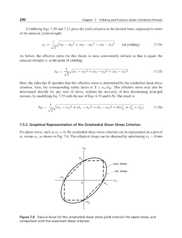
For plane stress, such as σ 3 = 0, the octahedral shear stress criterion can be represented on a plot of
σ 1 versus σ 2 , as shown in Fig. 7.8. This elliptical shape can be obtained by substituting σ 3 = 0into
σ
2
σ
o
max. shear
oct. shear
–σ
o σ
0 σ 1
o
–σ
o
Figure 7.8 Failure locus for the octahedral shear stress yield criterion for plane stress, and
comparison with the maximum shear criterion.