
Page 283 - Mechanical Behavior of Materials
P. 283
284 Chapter 7 Yielding and Fracture under Combined Stresses
where the subscript S specifies the maximum shear stress criterion. The safety factor against yielding
is then
σ o
X = (7.22)
¯ σ S
7.4.2 Graphical Representation of the Maximum Shear Stress Criterion
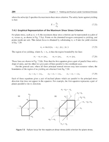
For plane stress, such as σ 3 = 0, the maximum shear stress criterion can be represented on a plot of
σ 1 versus σ 2 , as shown in Fig. 7.5(a). Points on the distorted hexagon correspond to yielding, and
points inside are safe. This failure locus is obtained by substituting σ 3 = 0 into the yield criterion
of Eq. 7.20:
σ o = MAX(|σ 1 − σ 2 | , |σ 2 | , |σ 1 |) (7.23)
The region of no yielding, where ¯σ S <σ o , is thus the region bounded by the lines
σ 1 − σ 2 =±σ o , σ 2 =±σ o , σ 1 =±σ o (7.24)
These lines are shown in Fig. 7.5(b). Note that the first equation gives a pair of parallel lines with a
slope of unity, and the other two give pairs of lines parallel to the coordinate axes.
For the general case, where all three principal normal stresses may have nonzero values, the
boundaries of the region of no yielding are obtained from Eq. 7.20:
σ 1 − σ 2 =±σ o , σ 2 − σ 3 =±σ o , σ 1 − σ 3 =±σ o (7.25)
Each of these equations gives a pair of inclined planes which are parallel to the principal stress
direction that does not appear in the equation. For example, the first equation represents a pair of
planes parallel to the σ 3 direction.
σ − σ = − σ o
2
1
σ = σ
σ 2 1 o
(a) (b) σ
2 σ = σ o
2
σ
o
σ − σ = σ o
2
1
− σ o
0 σ σ 1 0 σ 1
o
− σ
o
σ = − σ
2 o
σ = −σ
1 o
Figure 7.5 Failure locus for the maximum shear stress yield criterion for plane stress.