
Page 430 - Mechanical Behavior of Materials
P. 430
Section 9.4 Fatigue Testing 431
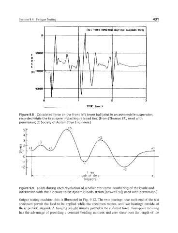
Figure 9.8 Calculated force on the front left lower ball joint in an automobile suspension,
recorded while the tires were impacting railroad ties. (From [Thomas 87]; used with
permission; c Society of Automotive Engineers.)
Figure 9.9 Loads during each revolution of a helicopter rotor. Feathering of the blade and
interaction with the air cause these dynamic loads. (From [Boswell 59]; used with permission.)
fatigue testing machine; this is illustrated in Fig. 9.12. The two bearings near each end of the test
specimen permit the load to be applied while the specimen rotates, and two bearings outside of
these provide support. A hanging weight usually provides the constant force. Four-point bending
has the advantage of providing a constant bending moment and zero shear over the length of the