
Page 435 - Mechanical Behavior of Materials
P. 435
436 Chapter 9 Fatigue of Materials: Introduction and Stress-Based Approach
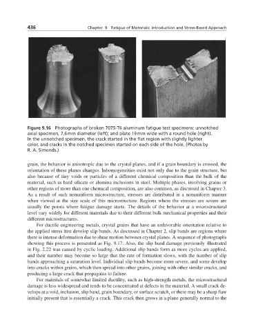
Figure 9.16 Photographs of broken 7075-T6 aluminum fatigue test specimens: unnotched
axial specimen, 7.6 mm diameter (left); and plate 19 mm wide with a round hole (right).
In the unnotched specimen, the crack started in the flat region with slightly lighter
color, and cracks in the notched specimen started on each side of the hole. (Photos by
R. A. Simonds.)
grain, the behavior is anisotropic due to the crystal planes, and if a grain boundary is crossed, the
orientation of these planes changes. Inhomogeneities exist not only due to the grain structure, but
also because of tiny voids or particles of a different chemical composition than the bulk of the
material, such as hard silicate or alumina inclusions in steel. Multiple phases, involving grains or
other regions of more than one chemical composition, are also common, as discussed in Chapter 3.
As a result of such nonuniform microstructure, stresses are distributed in a nonuniform manner
when viewed at the size scale of this microstructure. Regions where the stresses are severe are
usually the points where fatigue damage starts. The details of the behavior at a microstructural
level vary widely for different materials due to their different bulk mechanical properties and their
different microstructures.
For ductile engineering metals, crystal grains that have an unfavorable orientation relative to
the applied stress first develop slip bands. As discussed in Chapter 2, slip bands are regions where
there is intense deformation due to shear motion between crystal planes. A sequence of photographs
showing this process is presented as Fig. 9.17. Also, the slip band damage previously illustrated
in Fig. 2.22 was caused by cyclic loading. Additional slip bands form as more cycles are applied,
and their number may become so large that the rate of formation slows, with the number of slip
bands approaching a saturation level. Individual slip bands become more severe, and some develop
into cracks within grains, which then spread into other grains, joining with other similar cracks, and
producing a large crack that propagates to failure.
For materials of somewhat limited ductility, such as high-strength metals, the microstructural
damage is less widespread and tends to be concentrated at defects in the material. A small crack de-
velops at a void, inclusion, slip band, grain boundary, or surface scratch, or there may be a sharp flaw
initially present that is essentially a crack. This crack then grows in a plane generally normal to the