
Page 440 - Mechanical Behavior of Materials
P. 440
440 Chapter 9 Fatigue of Materials: Introduction and Stress-Based Approach
Figure 9.20 Fatigue failure of an aluminum alloy airplane propeller. The failure began
at a small gouge on the bottom edge, approximately 2 cm from the right end of the scale.
(Photo by R. A. Simonds; sample loaned for photo by Prof. J. L. Lytton of Virginia Tech,
Blacksburg, VA.)
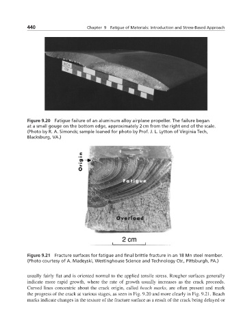
Figure 9.21 Fracture surfaces for fatigue and final brittle fracture in an 18 Mn steel member.
(Photo courtesy of A. Madeyski, Westinghouse Science and Technology Ctr., Pittsburgh, PA.)
usually fairly flat and is oriented normal to the applied tensile stress. Rougher surfaces generally
indicate more rapid growth, where the rate of growth usually increases as the crack proceeds.
Curved lines concentric about the crack origin, called beach marks, are often present and mark
the progress of the crack at various stages, as seen in Fig. 9.20 and more clearly in Fig. 9.21. Beach
marks indicate changes in the texture of the fracture surface as a result of the crack being delayed or