
Page 186 - Introduction to Marine Engineering
P. 186
172 Refrigeration, air conditioning and ventilation
Cargo refrigeration
Refrigerated cargo vessels usually require a system which provides for
various spaces to be cooled to different temperatures. The arrange-
ments adopted can be considered in three parts: the central primary
refrigerating plant, the brine circulating system, and the air circulating
system for cooling the cargo in the hold.
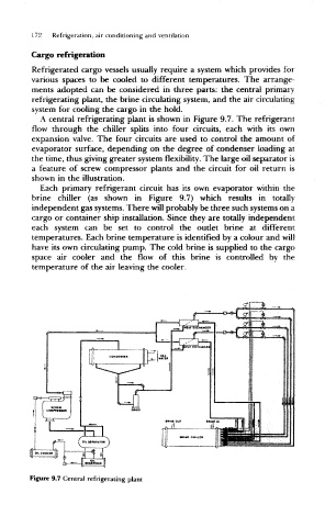
A central refrigerating plant is shown in Figure 9.7. The refrigerant
flow through the chiller splits into four circuits, each with its own
expansion valve. The four circuits are used to control the amount of
evaporator surface, depending on the degree of condenser loading at
the time, thus giving greater system flexibility. The large oil separator is
a feature of screw compressor plants and the circuit for oil return is
shown in the illustration.
Each primary refrigerant circuit has its own evaporator within the
brine chiller (as shown in Figure 9.7) which results in totally
independent gas systems. There will probably be three such systems on a
cargo or container ship installation. Since they are totally independent
each system can be set to control the outlet brine at different
temperatures. Each brine temperature is identified by a colour and will
have its own circulating pump. The cold brine is supplied to the cargo
space air cooler and the flow of this brine is controlled by the
temperature of the air leaving the cooler.
Figure 9.7 Central refrigerating plant