
Page 487 - Moving the Earth_ The Workbook of Excavation
P. 487
BLASTING AND TUNNELING
BLASTING AND TUNNELING 9.87
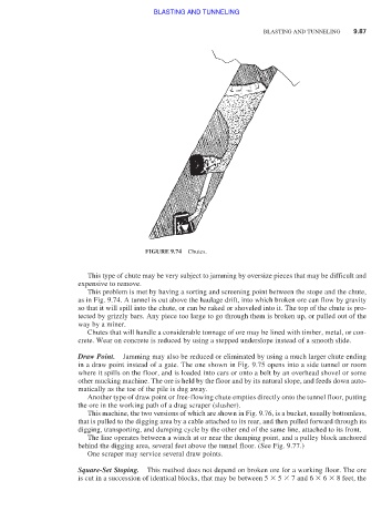
FIGURE 9.74 Chutes.
This type of chute may be very subject to jamming by oversize pieces that may be difficult and
expensive to remove.
This problem is met by having a sorting and screening point between the stope and the chute,
as in Fig. 9.74. A tunnel is cut above the haulage drift, into which broken ore can flow by gravity
so that it will spill into the chute, or can be raked or shoveled into it. The top of the chute is pro-
tected by grizzly bars. Any piece too large to go through them is broken up, or pulled out of the
way by a miner.
Chutes that will handle a considerable tonnage of ore may be lined with timber, metal, or con-
crete. Wear on concrete is reduced by using a stepped underslope instead of a smooth slide.
Draw Point. Jamming may also be reduced or eliminated by using a much larger chute ending
in a draw point instead of a gate. The one shown in Fig. 9.75 opens into a side tunnel or room
where it spills on the floor, and is loaded into cars or onto a belt by an overhead shovel or some
other mucking machine. The ore is held by the floor and by its natural slope, and feeds down auto-
matically as the toe of the pile is dug away.
Another type of draw point or free-flowing chute empties directly onto the tunnel floor, putting
the ore in the working path of a drag scraper (slusher).
This machine, the two versions of which are shown in Fig. 9.76, is a bucket, usually bottomless,
that is pulled to the digging area by a cable attached to its rear, and then pulled forward through its
digging, transporting, and dumping cycle by the other end of the same line, attached to its front.
The line operates between a winch at or near the dumping point, and a pulley block anchored
behind the digging area, several feet above the tunnel floor. (See Fig. 9.77.)
One scraper may service several draw points.
Square-Set Stoping. This method does not depend on broken ore for a working floor. The ore
is cut in a succession of identical blocks, that may be between 5 5 7 and 6 6 8 feet, the