
Page 175 - Petroleum Production Engineering, A Computer-Assisted Approach
P. 175
Guo, Boyun / Computer Assited Petroleum Production Engg 0750682701_chap12 Final Proof page 171 4.1.2007 2:43pm Compositor Name: SJoearun
SUCKER ROD PUMPING 12/171
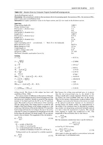
Table 12.2 Solution Given by Computer Program SuckerRodPumpingLoad.xls
SuckerRodPumpingLoad.xls
Description: This spreadsheet calculates the maximum allowable pumping speed, the maximum PRL, the minimum PRL,
peak torque, and counterbalance load.
Instruction: (1) Update parameter values in the Input section; and (2) view result in the Solution section.
Input data
Pump setting depth (D): 3,000 ft
Plunger diameter (d p ): 2.5 in.
Rod section 1, diameter (d r1 ): 1 in.
Length (L 1 ): 0 ft
Rod section 2, diameter (d r2 ): 0.875 in.
Length (L 2 ): 3,000 ft
Rod section 3, diameter (d r3 ): 0.75 in.
Length (L 3 ): 0 ft
Rod section 4, diameter (d r4 ): 0.5 in.
Length (L 4 ): 0 ft
Type of pumping unit (1 ¼ conventional; 1 ¼ Mark II or Air-balanced): 1
Beam dimension 1 (d 1 ) 96.05 in.
Beam dimension 2 (d 2 ) 111 in.
Crank length (c): 37 in.
Crank to pitman ratio (c/h): 0.33
Oil gravity (API): 25 8API
Maximum allowable acceleration factor (L): 0.4
Solution
S ¼ 2c d 2 ¼ 85.52 in.
d 1
q ffiffiffiffiffiffiffiffiffiffiffiffiffiffi
N ¼ 70471:2L ¼ 22 SPM
S(1 h ) c
pd 2
A p ¼ p ¼ 4.91 in: 2
4
pd 2
A r ¼ r ¼ 0.60 in.
4
W f ¼ S f (62:4) DA p ¼ 5,770 lb
144
W r ¼ g s DA r ¼ 6,138 lb
144
2
F 1 ¼ SN (1 h ) c ¼ 0.7940 8
70,471:2
PRL max ¼ W f S f (62:4) W r þ W r þ W r F 1 ¼ 16,076 lb
g s
1
T ¼ SW f þ 2SN 2 W r ¼ 280,056 lb
4 70,471:2
2
SN (1 h ) c
F 2 ¼ 70,471:2 ¼ 0.40
PRL min ¼ S f (62:4) W r þ W r W r F 2 ¼ 2,976 lb
g s
1
C ¼ (PRL max þ PRL min ) ¼ 9,526 lb
2
tubing stretch. The theory in this subject has been well But because the tubing cross-sectional area A t is greater
established (Nind, 1964). than the rod cross-sectional area A r , the stretch of the
Two major sources of difference in the motion of the pol- tubing is small and is usually neglected. However, the tub-
ishedrodandtheplungerareelasticstretch(elongation)ofthe ing stretch can cause problems with wear on the casing.
rod string and overtravel. Stretch is caused by the periodic Thus, for this reason a tubing anchor is almost always used.
transfer of the fluid load from the SV to the TV and back Plunger overtravel at the bottom of the stroke is a result
again. The result is a function of the stretch of the rod string of the upward acceleration imposed on the downward-
and the tubing string. Rod string stretch is caused by the moving sucker rod elastic system. An approximation to
weight of the fluid column in the tubing coming on to the the extent of the overtravel may be obtained by consider-
rodstringatthebottomofthestrokewhentheTVcloses(this ing a sucker rod string being accelerated vertically upward
load is removed from the rod string at the top of the stroke at a rate n times the acceleration of gravity. The vertical
whentheTVopens).Itisapparentthattheplungerstrokewill force required to supply this acceleration is nW r . The
be less than the polished rod stroke length S by an amount magnitude of the rod stretch due to this force is
equal to the rod stretch. The magnitude of the rod stretch is
W r D r
dl o ¼ n (ft): (12:38)
W f D r A r E
dl r ¼ , (12:36)
A r E But the maximum acceleration term n can be written as
where SN 1 c
2
n ¼ h
W f ¼ weight of fluid (lb) 70,471:2
D r ¼ length of rod string (ft) so that Eq. (12.38) becomes
2
A r ¼ cross-sectional area of rods (in: )
2
6
2
E ¼ modulus of elasticity of steel (30 10 lb=in: ). W r D r SN 1 h c
dl o ¼ (ft), (12:39)
Tubing stretch can be expressed by a similar equation: A r E 70,471:2
where again the plus sign applies to conventional units and
W f D t the minus sign to air-balanced units.
dl t ¼ (12:37)
A t E