
Page 177 - Petroleum Production Engineering, A Computer-Assisted Approach
P. 177
Guo, Boyun / Computer Assited Petroleum Production Engg 0750682701_chap12 Final Proof page 173 4.1.2007 2:43pm Compositor Name: SJoearun
SUCKER ROD PUMPING 12/173
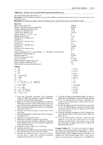
Table 12.3 Solution Given by SuckerRodPumpingFlowrate&Power.xls
SuckerRodPumpingFlowRate&Power.xls
Description: This spreadsheet calculates expected deliverability and required prime mover power for a given sucker rod
pumping system.
Instruction: (1) Update parameter values in the Input section; and (2) view result in the Solution section.
Input data
Pump setting depth (D): 4,000 ft
Depth to the liquid level in annulus (H): 4,000 ft
Flowing tubing head pressure (p tf ): 100 ft
Tubing outer diameter (d to ): 3.5 in.
Tubing inner diameter (d ti ): 2.995 in.
Tubing anchor (1 ¼ yes; 0 ¼ no): 0
Plunger diameter (d p ): 2.5 in.
Rod section 1, diameter (d r1 ): 1 in.
Length (L 1 ): 0 ft
Rod section 2, diameter (d r2 ): 0.875 in.
Length (L 2 ): 0 ft
Rod section 3, diameter (d r3 ): 0.75 in.
Length (L 3 ): 4,000 ft
Rod section 4, diameter (d r4 ): 0.5 in.
Length (L 4 ): 0 ft
Type of pumping unit (1 ¼ conventional; 1 ¼ Mark II or Air-balanced): 1
Polished rod stroke length (S) 86 in.
Pumping speed (N) 22 spm
Crank to pitman ratio (c/h): 0.33 8
Oil gravity (API): 25 8API
Fluid formation volume factor (B o ): 1.2 rb/stb
Pump volumetric efficiency (E v ): 0.8
Safety factor to prime mover power (F s ): 1.35
Solution
2
A t ¼ pd t ¼ 2.58 in: 2
4 2
A p ¼ pd p ¼ 4.91 in: 2
4
2
A r ¼ pd r ¼ 0.44 in.
4
W f ¼ S f (62:4) DA p ¼ 7,693 lb
144
W r ¼ g s DA r ¼ 6,013 lb
144
M ¼ 1 c h h i ¼ 1.33
2
SN M W r
S p ¼ S 12D W f A r 1 þ A t 1 70471:2 A r ¼ 70 in.
E
q ¼ 0:1484 A p NS p E v ¼ 753 sbt/day
B o
L N ¼ H þ p tf ¼ 4,255 ft
0:433g l
6
P h ¼ 7:36 10 qg l L N ¼ 25.58 hp
7
P f ¼ 6:31 10 W r SN ¼ 7.2 hp
P pm ¼ F s (P h þ P f ) ¼ 44.2 hp
1. From the maximum anticipated fluid production 13. Calculate the ideal counterbalance effect and check it
(based on IPR) and estimated volumetric efficiency, againstthecounterbalanceavailablefortheunitselected.
calculate required pump displacement. 14. From the manufacturer’s literature, determine the
2. Based on well depth and pump displacement, determine position of the counterweight to obtain the ideal coun-
API rating and stroke length of the pumping unit to be terbalance effect.
used.ThiscanbedoneusingeitherFig.12.8orTable12.4. 15. On the assumption that the unit will be no more than
3. Select tubing size, plunger size, rod sizes, and pumping 5% out of counterbalance, calculate the peak torque
speed from Table 12.4. on the gear reducer and check it against the API rating
4. Calculate the fractional length of each section of the of the unit selected.
rod string. 16. Calculate hydraulic horsepower, friction horsepower,
5. Calculate the length of each section of the rod string to and brake horsepower of the prime mover. Select the
the nearest 25 ft. prime mover.
6. Calculate the acceleration factor. 17. From the manufacturer’s literature, obtain the gear
7. Determine the effective plunger stroke length. reduction ratio and unit sheave size for the unit
8. Using the estimated volumetric efficiency, determine selected, and the speed of the prime mover. From
the probable production rate and check it against the this, determine the engine sheave size to obtain the
desired production rate. desired pumping speed.
9. Calculate the dead weight of the rod string.
10. Calculate the fluid load. Example Problem 12.3 A well is to be put on a sucker
11. Determine peak polished rod load and check it against rod pump. The proposed pump setting depth is 3,500 ft.
the maximum beam load for the unit selected. The anticipated production rate is 600 bbl/day oil of 0.8
12. Calculate the maximum stress at the top of each rod specific gravity against wellhead pressure 100 psig. It is
size and check it against the maximum permissible assumed that the working liquid level is low, and a
working stress for the rods to be used. sucker rod string having a working stress of 30,000 psi is