
Page 181 - Petroleum Production Engineering, A Computer-Assisted Approach
P. 181
Guo, Boyun / Computer Assited Petroleum Production Engg 0750682701_chap12 Final Proof page 177 4.1.2007 2:43pm Compositor Name: SJoearun
SUCKER ROD PUMPING 12/177
two lugs, which are attached to the winged nut, which run The use of the pump dynagraph involves pulling the
in vertical grooves in the cover tube. The stylus is mounted rods and pump from the well bath to install the instrument
on a third tube, which is free to rotate and is connected by and to recover the recording tube. Also, the dynagraph
a self-aligning bearing to the upper end of the calibrated cannot be used in a well equipped with a tubing pump.
rod. Lugs attached to the cover tube run in spiral grooves Thus, the dynagraph is more a research instrument than an
cut in the outer surface of the rotating tube. Consequently, operational device. Once there is knowledge from a dyna-
vertical motion of the plunger assembly relative to the graph, surface dynamometer cards can be interpreted.
barrel results in rotation of the third tube, and the stylus The surface, or polished rod, dynamometer is a device
cuts a horizontal line on a recording tube. that records the motion of (and its history) the polished
Any change in plunger loading causes a change in length rod during the pumping cycle. The rod string is forced by
of the section of the calibrated rod between the winged nut the pumping unit to follow a regular time versus position
supporting the recording tube and the self-aligning bearing pattern. However, the polished rod reacts with the load-
supporting the rotating tube (so that a vertical line is cut ings (on the rod string) that are imposed by the well.
on the recording tube by the stylus). When the pump is in The surface dynamometer cards record the history of
operation, the stylus traces a series of cards, one on top of the variations in loading on the polished rod during a
the other. To obtain a new series of cards, the polished rod cycle. The cards have three principal uses:
at the well head is rotated. This rotation is transmitted to
the plunger in a few pump strokes. Because the recording a. To obtain information that can be used to determine
tube is prevented from rotating by the winged nut lugs that load, torque, and horsepower changes required of the
run in the cover tube grooves, the rotation of the sucker pump equipment
rod string causes the winged nut to travel—upward or b. To improve pump operating conditions such as pump
downward depending on the direction of rotation—on speed and stroke length
c. To check well conditions after installation of equipment
the threaded calibrated rod. Upon the completion of a
to prevent or diagnose various operating problems (like
series of tests, the recording tube (which is 36 in. long) is
pounding, etc.)
removed.
It is important to note that although the bottom-hole
Surface instruments can be mechanical, hydraulic, and
dynagraph records the plunger stroke and variations in
electrical. One of the most common mechanical instru-
plunger loading, no zero line is obtained. Thus, quantita-
ments is a ring dynamometer installed between the hanger
tive interpretation of the cards becomes somewhat specu-
bar and the polished rod clamp in such a manner as the
lative unless a pressure element is run with the dynagraph. ring may carry the entire well load. The deflection of the
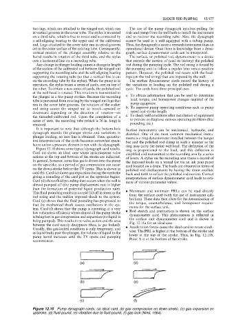
Figure 12.10 shows some typical dynagraph card results. ring is proportional to the load, and this deflection is
Card (a) shows an ideal case where instantaneous valve amplified and transmitted to the recording arm by a series
actions at the top and bottom of the stroke are indicated. of levers. A stylus on the recording arm traces a record of
In general, however, some free gas is drawn into the pump the imposed loads on a waxed (or via an ink pen) paper
on the upstroke, so a period of gas compression can occur card located on a drum. The loads are obtained in terms of
on the down-stroke before the TV opens. This is shown in polished rod displacements by having the drum oscillate
card (b). Card (c) shows gas expansion during the upstroke back and forth to reflect the polished rod motion. Correct
giving a rounding of the card just as the upstroke begins. interpretation of surface dynamometer card leads to esti-
Card (d) shows fluid pounding that occurs when the well is mate of various parameter values.
almost pumped off (the pump displacement rate is higher
than the formation of potential liquid production rate).
This fluid pounding results in a rapid fall off in stress in the . Maximum and minimum PRLs can be read directly
rod string and the sudden imposed shock to the system. from the surface card (with the use of instrument cali-
Card (e) shows that the fluid pounding has progressed so bration). These data then allow for the determination of
that the mechanical shock causes oscillations in the sys- the torque, counterbalance, and horsepower require-
tem. Card (f) shows that the pump is operating at a very ments for the surface unit.
low volumetric efficiency where almost all the pump stroke . Rod stretch and contraction is shown on the surface
is being lost in gas compression and expansion (no liquid is dynamometer card. This phenomenon is reflected in
being pumped). This results in no valve action and the area the surface unit dynamometer card and is shown in
between the card nearly disappears (thus, is gas locked). Fig. 12.11a for an ideal case.
Usually, this gas-locked condition is only temporary, and . Acceleration forces cause the ideal card to rotate clock-
as liquid leaks past the plunger, the volume of liquid in the wise. The PRL is higher at the bottom of the stroke and
lower at the top of the stroke. Thus, in Fig. 12.11b,
pump barrel increases until the TV opens and pumping
Point A is at the bottom of the stroke.
recommences.
Figure 12.10 Pump dynagraph cards: (a) ideal card, (b) gas compression on down-stroke, (c) gas expansion on
upstroke, (d) fluid pound, (e) vibration due to fluid pound, (f) gas lock (Nind, 1964).