
Page 186 - Petroleum Production Engineering, A Computer-Assisted Approach
P. 186
Guo, Boyun / Computer Assited Petroleum Production Engg 0750682701_chap13 Final Proof page 182 3.1.2007 9:07pm Compositor Name: SJoearun
13/182 ARTIFICIAL LIFT METHODS
13.1 Introduction on the tubing string. There are four principal advantages
to be gained by the use of multiple valves in a well:
Gas lift technology increases oil production rate by injec-
tion of compressed gas into the lower section of tubing 1. Deeper gas injection depths can be achieved by using
through the casing–tubing annulus and an orifice installed valves for wells with fixed surface injection pressures.
in the tubing string. Upon entering the tubing, the com- 2. Variation in the well’s productivity can be obtained by
pressed gas affects liquid flow in two ways: (a) the energy selectively injecting gas valves set at depths ‘‘higher’’ or
of expansion propels (pushes) the oil to the surface and ‘‘lower’’ in the tubing string.
(b) the gas aerates the oil so that the effective density of the 3. Gas volumes injected into the well can be ‘‘metered’’
fluid is less and, thus, easier to get to the surface. into the well by the valves.
There are four categories of wells in which a gas lift can 4. Intermittent gas injection at progressively deeper set
be considered:
valves can be carried out to ‘‘kick off’’ a well to either
1. High productivity index (PI), high bottom-hole pres- continuous or intermittent flow.
sure wells
2. High PI, low bottom-hole pressure wells A continuous gas lift operation is a steady-state flow of
3. Low PI, high bottom-hole pressure wells the aerated fluid from the bottom (or near bottom) of the
4. Low PI, low bottom-hole pressure wells well to the surface. Intermittent gas lift operation is char-
acterized by a start-and-stop flow from the bottom
Wells having a PI of 0.50 or less are classified as low (or near bottom) of the well to the surface. This is unsteady
productivity wells. Wells having a PI greater than 0.50 are state flow.
classified as high productivity wells. High bottom-hole In continuous gas lift, a small volume of high-pressure
pressures will support a fluid column equal to 70% of the gas is introduced into the tubing to aerate or lighten the
well depth. Low bottom-hole pressures will support a fluid fluid column. This allows the flowing bottom-hole pres-
column less than 40% of the well depth. sure with the aid of the expanding injection gas to deliver
Gas lift technology has been widely used in the oil fields liquid to the surface. To accomplish this efficiently, it is
that produce sandy and gassy oils. Crooked/deviated holes desirable to design a system that will permit injection
present no problem. Well depth is not a limitation. It is also through a single valve at the greatest depth possible with
applicable to offshore operations. Lifting costs for a large the available injection pressure.
number of wells are generally very low. However, it requires Continuous gas lift method is used in wells with a
lift gas within or near the oil fields. It is usually not efficient high PI ( 0:5 stb=day=psi) and a reasonably high reser-
in lifting small fields with a small number of wells if gas voir pressure relative to well depth. Intermittent gas
compression equipment is required. Gas lift advancements lift method is suitable to wells with (1) high PI and
in pressure control and automation systems have enabled low reservoir pressure or (2) low PI and low reservoir
the optimization of individual wells and gas lift systems. pressure.
The type of gas lift operation used, continuous or
intermittent, is also governed by the volume of fluids
13.2 Gas Lift System to be produced, the available lift gas as to both volume
A complete gas lift system consists of a gas compression and pressure, and the well reservoir’s conditions such as
station, a gas injection manifold with injection chokes and the case when the high instantaneous BHP drawdown
time cycle surface controllers, a tubing string with instal- encountered with intermittent flow would cause exces-
lations of unloading valves and operating valve, and a sive sand production, or coning, and/or gas into the
down-hole chamber. wellbore.
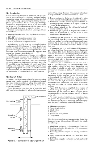
Figure 13.1 depicts a configuration of a gas-lifted well Figure 13.2 illustrates a simplified flow diagram of
with installations of unloading valves and operating valve a closed rotary gas lift system for a single well in an
intermittent gas lift operation. The time cycle surface
controller regulates the start-and-stop injection of lift gas
to the well.
Production For proper selection, installation, and operations of gas
lift systems, the operator must know the equipment and
Gas inlet the fundamentals of gas lift technology. The basic equip-
ment for gas lift technology includes the following:
a. Main operating valves
b. Wire-line adaptations
c. Check valves
d. Mandrels
e. Surface control equipment
Unloading f. Compressors
valves
This chapter covers basic system engineering design fun-
damentals for gas lift operations. Relevant topics include
the following:
1. Liquid flow analysis for evaluation of gas lift potential
Operating 2. Gas flow analysis for determination of lift gas compres-
valve sion requirements
3. Unloading process analysis for spacing subsurface
valves
4. Valve characteristics analysis for subsurface valve
selection
5. Installation design for continuous and intermittent lift
Figure 13.1 Configuration of a typical gas lift well. systems.