
Page 187 - Petroleum Production Engineering, A Computer-Assisted Approach
P. 187
Guo, Boyun / Computer Assited Petroleum Production Engg 0750682701_chap13 Final Proof page 183 3.1.2007 9:07pm Compositor Name: SJoearun
GAS LIFT 13/183
Time cycle
surface controller
Flowline
Separator
Stock Intermittent Injection
tank gas lift well gas line
By-pass regulator
Vent or
sales line
regulator
Suction regulator
Compressor
station
Low pressure High pressure
system system
Make-up gas line for charging system
Figure 13.2 A simplified flow diagram of a closed rotary gas lift system for single intermittent well.
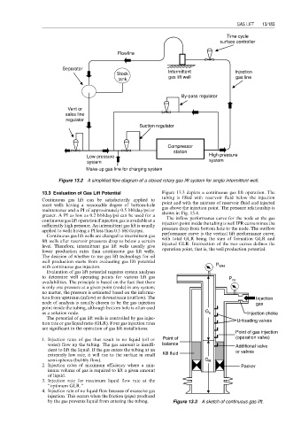
13.3 Evaluation of Gas Lift Potential Figure 13.3 depicts a continuous gas lift operation. The
tubing is filled with reservoir fluid below the injection
Continuous gas lift can be satisfactorily applied to
most wells having a reasonable degree of bottom-hole point and with the mixture of reservoir fluid and injected
maintenance and a PI of approximately 0.5 bbl/day/psi or gas above the injection point. The pressure relationship is
greater. A PI as low as 0.2 bbl/day/psi can be used for a shown in Fig. 13.4.
continuous gas lift operation if injection gas is available at a The inflow performance curve for the node at the gas
sufficiently high pressure. An intermittent gas lift is usually injection point inside the tubing is well IPR curve minus the
applied to wells having a PI less than 0.5 bbl/day/psi. pressure drop from bottom hole to the node. The outflow
Continuous gas lift wells are changed to intermittent gas performance curve is the vertical lift performance curve,
with total GLR being the sum of formation GLR and
lift wells after reservoir pressures drop to below a certain injected GLR. Intersection of the two curves defines the
level. Therefore, intermittent gas lift wells usually give
operation point, that is, the well production potential.
lower production rates than continuous gas lift wells.
The decision of whether to use gas lift technology for oil
well production starts from evaluating gas lift potential
with continuous gas injection. P WH
Evaluation of gas lift potential requires system analyses
to determine well operating points for various lift gas P
availabilities. The principle is based on the fact that there cs
is only one pressure at a given point (node) in any system;
no matter, the pressure is estimated based on the informa-
tion from upstream (inflow) or downstream (outflow). The Injection
node of analysis is usually chosen to be the gas injection gas
point inside the tubing, although bottom hole is often used
as a solution node. G u Injection choke
The potential of gas lift wells is controlled by gas injec- Unloading valves
tion rate or gas liquid ratio (GLR). Four gas injection rates
are significant in the operation of gas lift installations:
Point of gas injection
1. Injection rates of gas that result in no liquid (oil or Point of (operation valve)
water) flow up the tubing. The gas amount is insuffi- balance Additional valve
cient to lift the liquid. If the gas enters the tubing at an or valves
extremely low rate, it will rise to the surface in small Kill fluid
semi-spheres (bubbly flow). G R
2. Injection rates of maximum efficiency where a min- Packer
imum volume of gas is required to lift a given amount
of liquid.
3. Injection rate for maximum liquid flow rate at the
‘‘optimum GLR.’’
4. Injection rate of no liquid flow because of excessive gas
injection. This occurs when the friction (pipe) produced
by the gas prevents liquid from entering the tubing. Figure 13.3 A sketch of continuous gas lift.