
Page 189 - Petroleum Production Engineering, A Computer-Assisted Approach
P. 189
Guo, Boyun / Computer Assited Petroleum Production Engg 0750682701_chap13 Final Proof page 185 3.1.2007 9:07pm Compositor Name: SJoearun
GAS LIFT 13/185
zone depth, and D v is the depth of the gas injection point. This example shows that increasing the gas injection rate
Based on the oil gravity of 26 8API, G R is calculated to be from 1 MMscf/day to 1.58 MMscf/day will not make a
0.39 psi/ft. D and D v are equal to 5,200 ft and 5,000 ft, significant difference in the oil production rate.
respectively in this problem.
The outflow performance curve for the gas injection
point can be determined based on 2.259-in. tubing ID, 13.4 Gas Lift Gas Compression Requirements
200 psia wellhead pressure, and the GLRs. The gas compression station should be designed to provide
an adequate gas lift gas flow rate at sufficiently high
a. Spreadsheet OptimumGLR.xls gives the following:
pressure. These gas flow rates and output pressures deter-
mine the required power of the compression station.
q (stb/d) GLR opt (scf/stb)
13.4.1 Gas Flow Rate Requirement
The total gas flow rate of the compression station should
400 4,500
600 3,200 be designed on the basis of gas lift at peak operating
800 2,400 condition for all the wells with a safety factor for system
leak consideration, that is,
Nw
X
Using these data to run computer program HagedornBrown- q g,total ¼ S f q g,inj i , (13:4)
Correlation.xls (on the CD attached to this book) gives i¼1
where
q (stb/day) p t (psia) q g ¼ total output gas flow rate of the compression
station, scf/day
400 603 S f ¼ safety factor, 1.05 or higher
600 676 N w ¼ number of wells.
800 752 The procedure for determination of lift gas injection
rate q g,inj to each well has been illustrated in Example Prob-
lem 13.1.
Figure 13.5 shows the system analysis plot given by
the computer program GasLiftPotential.xls. It indicates 13.4.2 Output Gas Pressure Requirement
an operating point of q ¼ 632 stb=day and p t,v ¼ 698 psia Kickoff of a dead well (non-natural flowing) requires
tubing pressure at the depth of injection. much higher compressor output pressures than the ulti-
The optimum GLR at the operating point is calculated mate goal of steady production (either by continuous gas
with interpolation as lift or by intermittent gas lift operations). Mobil compressor
3,200 2,400 trailers are used for the kickoff operations. The output
GLR opt,o ¼ 2,400 þ ð 800 632Þ pressure of the compression station should be designed
800 600
on the basis of the gas distribution pressure under normal
¼ 3,072 scf=stb: flow conditions, not the kickoff conditions. It can be
expressed as
The injection GLR is
p out ¼ S f p L , (13:5)
GLR inj ¼ 3,072 300 ¼ 2,772 scf=stb:
where
Then the required gas injection rate to the well can be
calculated: p out ¼ output pressure of the compression
station, psia
q g,inj ¼ (2,772)(632) ¼ 1,720,000 scf=day S f ¼ safety factor
p L ¼ pressure at the inlet of the gas
b. For a given amount of lift gas 1 MMscf/day, the GLR distribution line, psia.
can be calculated with Eq. (13.3) as
Starting from the tubing pressure at the valve ( p t,v ), the
pressure at the inlet of the gas distribution line can be
estimated based on the relationships of pressures along
q (stb/day) GLR (scf/stb)
the injection path. These relationships are discussed in
the following subsections.
400 2,800
600 1,967
800 1,550 13.4.2.1 Injection Pressure at Valve Depth
The injection pressure at valve depth in the casing side can
be expressed as
Using these data to run computer program Hagedorn-
BrownCorrelation.xls gives p c,v ¼ p t,v þ Dp v , (13:6)
where
p c,v ¼ casing pressure at valve depth, psia
q (stb/day) p t (psia) Dp v ¼ pressure differential across the operating valve
(orifice).
400 614
600 694 It is a common practice to use Dp v ¼ 100 psi. The
800 774 required size of the orifice can be determined using the
choke-flow equations presented in Subsection 13.4.2.3.
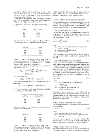
Figure 13.6 shows the system analysis plot given by
the computer program GasLiftPotential.xls. It indicates 13.4.2.2 Injection Pressure at Surface
an operating point of q ¼ 620 stb=day and p t ¼ 702 psia Accurate determination of the surface injection pressure
tubing pressure at the depth of injection. p c,s requires rigorous methods such as the Cullender and