
Page 192 - Petroleum Production Engineering, A Computer-Assisted Approach
P. 192
Guo, Boyun / Computer Assited Petroleum Production Engg 0750682701_chap13 Final Proof page 188 3.1.2007 9:07pm Compositor Name: SJoearun
13/188 ARTIFICIAL LIFT METHODS
( p dn ) can be assumed to be the surface injection pressure, rotary motion to reciprocation motion. A reciprocating
that is, compressor is designed for a certain range of compression
ratios through the selection of proper piston displacement
p dn ¼ p c,s ¼ 533 psia:
and clearance volume within the cylinder. This clearance
Assuming minimum sonic flow at the injection choke, the volume can be either fixed or variable, depending on
pressure upstream of the choke is calculated as the extent of the operation range and the percent of load
p dn variation desired. A typical reciprocating compressor
p up ¼ 1:82p dn ¼ (1:82)(533) ¼ 972 psia:
0:55 can deliver a volumetric gas flow rate up to 30,000 cubic
feet per minute (cfm) at a discharge pressure up to
The gas flow rate in each of the two gas distribution lines is 10,000 psig.
(2)(16)/(2), or 16 MMscf/day. Using the trial-and-error Rotary compressors are divided into two classes:
method, Eq. (13.18) gives
s ffiffiffiffiffiffiffiffiffiffiffiffiffiffiffiffiffiffiffiffiffiffiffiffiffiffiffiffiffiffiffiffiffiffiffiffiffiffiffiffiffiffiffiffiffiffiffiffiffiffiffiffiffiffiffiffiffiffiffiffiffiffiffiffiffiffiffiffiffiffiffiffiffiffiffiffiffiffiffiffiffiffiffiffiffiffiffiffiffiffiffiffiffiffiffiffiffiffiffiffi the centrifugal compressor and the rotary blower. A centri-
fugal compressor consists of a housing with flow passages, a
2
2
p L ¼ (972) þ (16,000)(14:7) (0:65)(530)(0:79)(1) rotating shaft on which the impeller is mounted, bearings,
0:433(60 þ 460) (4) 16=3 and seals to prevent gas from escaping along the shaft.
¼ 1,056 psia: Centrifugal compressors have few moving parts because
only the impeller and shaft rotate. Thus, its efficiency is
The required output pressure of the compressor is deter- high and lubrication oil consumption and maintenance
mined to be costs are low. Cooling water is normally unnecessary
because of lower compression ratio and lower friction
p out ¼ S f p L ¼ (1:1)(1,056) ¼ 1,162 psia:
loss. Compression rates of centrifugal compressors are
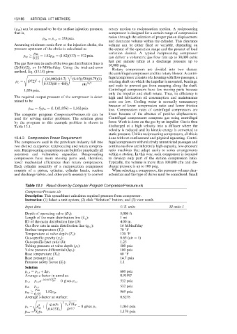
The computer program CompressorPressure.xls can be lower because of the absence of positive displacement.
used for solving similar problems. The solution given Centrifugal compressors compress gas using centrifugal
by the program to this example problem is shown in force. Work is done on the gas by an impeller. Gas is then
Table 13.1. discharged at a high velocity into a diffuser where the
velocity is reduced and its kinetic energy is converted to
static pressure. Unlike reciprocating compressors, all this is
13.4.3 Compression Power Requirement done without confinement and physical squeezing. Centri-
The compressors used in the petroleum industry fall into fugal compressors with relatively unrestricted passages and
two distinct categories: reciprocating and rotary compres- continuous flow are inherently high-capacity, low-pressure
sors. Reciprocating compressors are built for practically all ratio machines that adapt easily to series arrangements
pressures and volumetric capacities. Reciprocating within a station. In this way, each compressor is required
compressors have more moving parts and, therefore, to develop only part of the station compression ratio.
lower mechanical efficiencies than rotary compressors. Typically, the volume is more than 100,000 cfm and dis-
Each cylinder assembly of a reciprocation compressor charge pressure is up to 100 psig.
consists of a piston, cylinder, cylinder heads, suction When selecting a compressor, the pressure-volume char-
and discharge valves, and other parts necessary to convert acteristics and the type of driver must be considered. Small
Table 13.1 Result Given by Computer Program CompressorPressure.xls
CompressorPressure.xls
Description: This spreadsheet calculates required pressure from compressor.
Instruction: (1) Select a unit system; (2) click ‘‘Solution’’ button; and (3) view result.
Input data U.S. units SI units 1
Depth of operating valve (D v ): 5,000 ft
Length of the main distribution line (L g ): 1 mi
ID of the main distribution line (D): 4.00 in.
Gas flow rate in main distribution line (q g,l ): 16 MMscf/day
Surface temperature (T s ): 70 8F
Temperature at valve depth (T v ): 120 8F
Gas-specific gravity (g g ): 0:65 (air ¼ 1)
Gas-specific heat ratio (k): 1.25
Tubing pressure at valve depth ( p t ): 500 psia
Valve pressure differential (Dp v ): 100 psia
Base temperature (T b ): 60 8F
Base pressure ( p b ): 14.7 psia
Pressure safety factor (S f ): 1.1
Solution
p c,v ¼ p t,v þ Dp v 600 psia
Average z-factor in annulus: 0.9189?
g g D v
0:01875
p c,s p c,v e zT T 532 psia
z ¼ 0 gives p c,s
532 psia
p dn ¼ p c,s
p dn
p up ¼ 1:82p dn 969 psia
0:55
Average z-factor at surface: 0.8278
s ffiffiffiffiffiffiffiffiffiffiffiffiffiffiffiffiffiffiffiffiffiffiffiffiffiffiffiffiffiffiffiffiffiffiffiffiffiffiffiffiffiffiffiffiffiffiffiffiffiffiffiffiffiffi
2 TzzL
2
p L p þ q gM p b g g T g ¼ 0 gives p L 1,063 psia
up D 16=3
0:433T b
p out ¼ S f p L 1,170 psia