
Page 190 - Petroleum Production Engineering, A Computer-Assisted Approach
P. 190
Guo, Boyun / Computer Assited Petroleum Production Engg 0750682701_chap13 Final Proof page 186 3.1.2007 9:07pm Compositor Name: SJoearun
13/186 ARTIFICIAL LIFT METHODS
2,500 Inflow Pressure (psia)
Tubing Pressure at the Injection Depth (psia) 1,500
2,000
Outflow Pressure (psia)
1,000
500
0
−500
0 100 200 300 400 500 600 700 800 900
Liquid Flow Rate (stb/day)
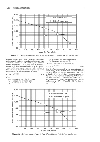
Figure 13.5 System analysis plot given by GasLiftPotential.xls for the unlimited gas injection case.
Smith method (Katz et al., 1959). The average temperature ¼ the average gas compressibility factor
z
z
and compressibility factor method also gives results with T T ¼ the average temperature, 8R.
acceptable accuracy. In both methods, the frictional Equation (13.7) can be rearranged to be
pressure losses in the annulus are considered. However, g g D v
because of the large cross-sectional area of the annular p c,s ¼ p c,v e 0:01875 : (13:8)
T
zT
z
space, the frictional pressure losses are often negligible.
Then the average temperature and compressibility factor Since the z factor also depends on p c,s , this equation can be
model degenerates to (Economides et al., 1994) solved for p c,s with a trial-and-error approach. Because
Eq. (13.8) involves exponential function that is difficult
g g Dv
0:01875
p c,v ¼ p c,s e , (13:7) to handle without a calculator, an approximation to
z
T
zT
the equation has been used traditionally. In fact, when
where Eq. (13.7) is expended as a Taylor series, and if common
p c,v ¼ casing pressure at valve depth, psia fluid properties for a natural gas and reservoir are consid-
p c,s ¼ casing pressure at surface, psia ered such as g g ¼ 0:7, z ¼ 0:9, and T ¼ 600 8R, it can be
T
z
g g ¼ gas specific gravity, air ¼ 1:0 approximated as
2,500 Inflow Pressure (psia)
Tubing Pressure at the Injection Depth (psia) 1,500
2,000
Outflow Pressure (psia)
1,000
500
−500 0
0 100 200 300 400 500 600 700 800 900
Liquid Flow Rate (stb/day)
Figure 13.6 System analysis plot given by GasLiftPotential.xls for the limited gas injection case.